
Industrial circulating water rapid sedimentation device

An industrial circulating water and settling device technology, which is applied to the feed/discharge device of the settling tank, sedimentation separation, water/sewage treatment, etc., can solve the problems of reduced purification efficiency, slow cooling speed, and reduced service life of purification membranes , to achieve the effect of increasing the collection amount, accelerating the rapid sedimentation process, and improving the cooling effect

Active Publication Date: 2019-10-18
衡阳市盛亚化工科技有限公司
View PDF13 Cites 1 Cited by
  • Summary
  • Abstract
  • Description
  • Claims
  • Application Information

AI Technical Summary

Problems solved by technology

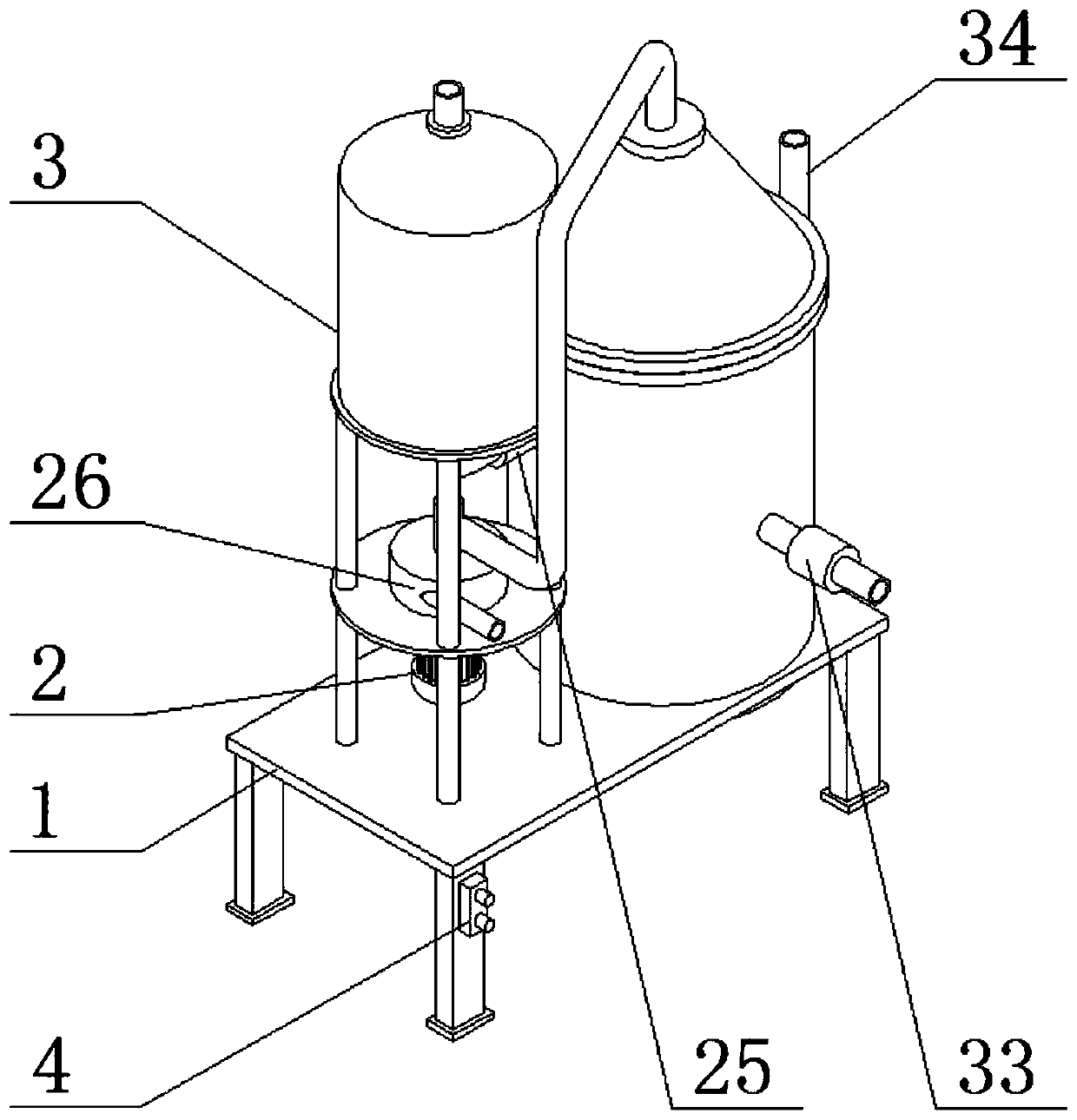
[0002] Because industrial circulating water contains a large amount of calcification, oxides, quicksand, dust, microbial bacteria and corrosive ions, these harmful substances usually cause harm to pipelines and equipment, so circulating water is usually purified by a purification treatment system before recycling In use, the current circulating water treatment system usually uses a filter membrane for purification, but there are still shortcomings in this method: 1. The circulating water contains a large amount of large particles, and the purification process uses the circulating water to filter and purify as a whole, which will reduce the purification efficiency; 2. Due to the existence of large particles of impurities, the filter membrane used for purification is easily blocked, thereby reducing the service life of the purification membrane; 3. The circulating water contains a lot of heat, which needs to be reused after heat exchange, and the current heat exchange usually uses surface The air cooling method is used for cooling, and the cooling speed is slow. In order to reduce the work burden of the purifier, the present invention provides a rapid settling device for industrial circulating water

Method used


Image

  • Industrial circulating water rapid sedimentation device
  • Industrial circulating water rapid sedimentation device
  • Industrial circulating water rapid sedimentation device

Examples


Embodiment approach

[0032] As a preferred embodiment of the present invention, the side wall of the stitching tube 15 is penetrated with a water tank, and a circular shaft 27 is welded in the water tank, and a wave-shaped swing plate 28 is set on the circular shaft 27. .

[0033] As a preferred embodiment of the present invention, a flow collecting cavity 29 is opened in the flow collecting plate 11 , and the flow collecting cavity 29 communicates with the delivery pipe 12 and the water suction pipe 13 .

[0034] As a preferred embodiment of the present invention, an air supply chamber 30 is opened in the air supply tray 21, and a water channel is opened on the side wall of the bottom of the air supply tank 22, and the air supply chamber 30 is passed through the water channel and the air supply channel. The air tank 22 is connected, the air supply tank 22 is coaxial with the confluence cover 16 , and an air inlet pipe 34 is welded on the bottom side wall of the air supply plate 21 .

[0035] As ...


PUM


Abstract

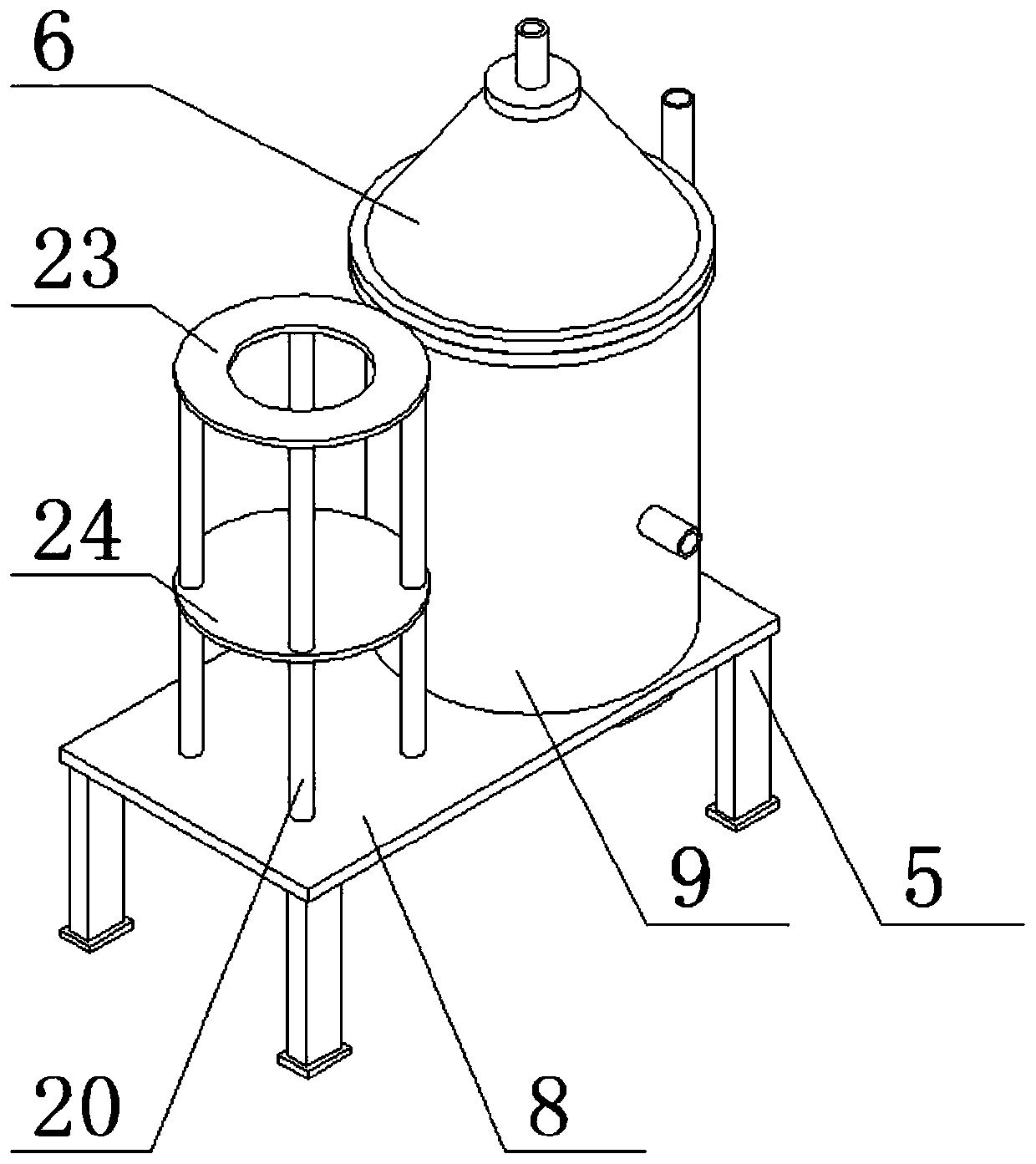
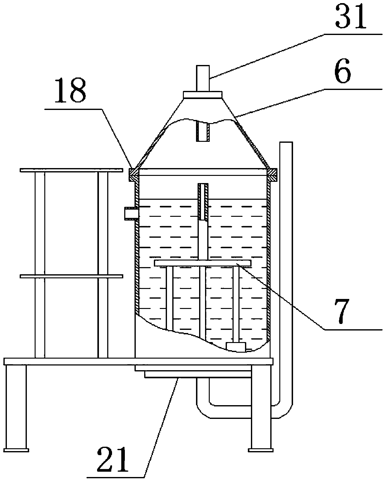
The invention discloses an industrial circulating water rapid sedimentation device. The device comprises a sedimentation combination, a negative pressure fan combination, a circulating water temporarystorage tank and a control box; the sedimentation combination comprises a sedimentation frame combination, a sedimentation tank sealing cover, needle-gap dense tube devices and an air supplementing plate; the sedimentation frame combination consists of a supporting platform plate and a settling tank; welding holes are formed in the top side wall of the supporting platform plate; and one end of the sedimentation tank penetrates through welding holes and is welded to the supporting platform plate. The sedimentation combination provided by the invention is of a closed structure and is internallyprovided with the needle-gap dense tube devices in a sleeve mode, and a needle-gap circulating device on the needle-gap dense tube devices can discharge water at the lower part of the sedimentation tank into the surface of circulating water in the sedimentation tank through a conveying pipe, so that up-and-down flowing of the water can be realized, large particles (calcified objects, oxides, quicksand particles and the like) in the circulating water can be accelerated to enter converge covers in the bottom needle-gap circulating devices, and thus the rapid sedimentation function of large-particle impurities is realized.

Description

technical field [0001] The invention relates to the technical field of industrial sewage treatment, in particular to a rapid settling device for industrial circulating water. Background technique [0002] Because industrial circulating water contains a large amount of calcification, oxides, quicksand, dust, microbial bacteria and corrosive ions, these harmful substances usually cause harm to pipelines and equipment, so circulating water is usually purified by a purification treatment system before recycling In use, the current circulating water treatment system usually uses a filter membrane for purification, but there are still shortcomings in this method: 1. The circulating water contains a large amount of large particles, and the purification process uses the circulating water to filter and purify as a whole, which will reduce the purification efficiency; 2. Due to the existence of large particles of impurities, the filter membrane used for purification is easily blocked,...

Claims


Application Information

Patent Timeline
Patent Type & Authority Applications(China)
IPC IPC(8): B01D21/00B01D21/24B01D21/30C02F1/52
CPCB01D21/0084B01D21/2433B01D21/30C02F1/52C02F2201/002C02F2301/063C02F2303/14
Inventor 张欢
Owner 衡阳市盛亚化工科技有限公司
Learn More