Manufacturing method of composite additional material

A technology of additive manufacturing and model components, which is applied in the field of composite additive manufacturing multi-functional multi-material model components, can solve the problems of single material and single function of model components, and achieve increased strength and reliability, improved reliability, The effect of increasing versatility

Inactive Publication Date: 2019-10-18
SHEN ZHEN QIANHAI SCICORE 3D TECH CO LTD
View PDF0 Cites 3 Cited by
  • Summary
  • Abstract
  • Description
  • Claims
  • Application Information

AI Technical Summary

Problems solved by technology

[0005] The present invention aims at the problem of single material and single function of the model components manufactured by the existing additive manufacturing method, and proposes a composite additive manufacturing method

Method used


Image

  • Manufacturing method of composite additional material
  • Manufacturing method of composite additional material
  • Manufacturing method of composite additional material

Examples


Embodiment 1

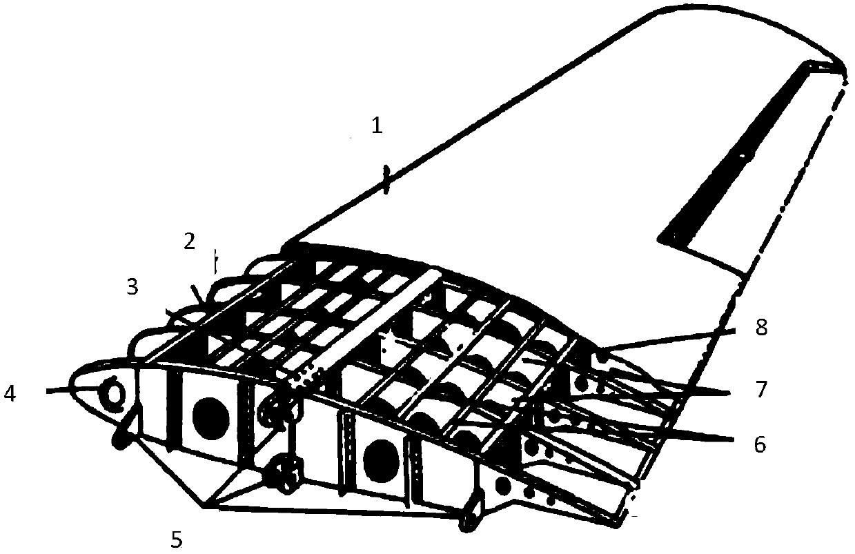
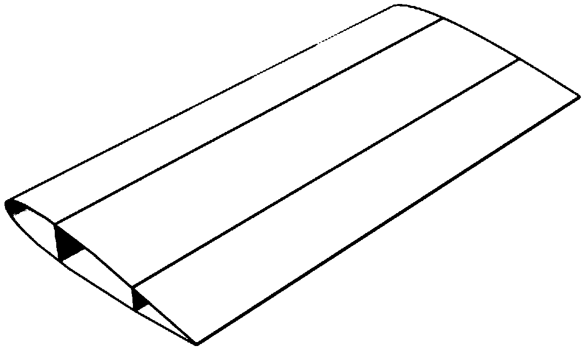
[0026] Taking the composite manufacturing of fixed-wing aircraft wings as an example, first use CAD to design the structure diagram of fixed-wing aircraft wings, as shown in figure 1 shown. In the wing structure, the positions of the skin 1, the front wall 2, the spar 3, the rib 4, the joint 5, the stringer 6, the rib 7 and the rear wall 8 on the wing are designed. Such as figure 2 A schematic diagram of the "programmable mold" for designing a fixed-wing aircraft wing is shown.

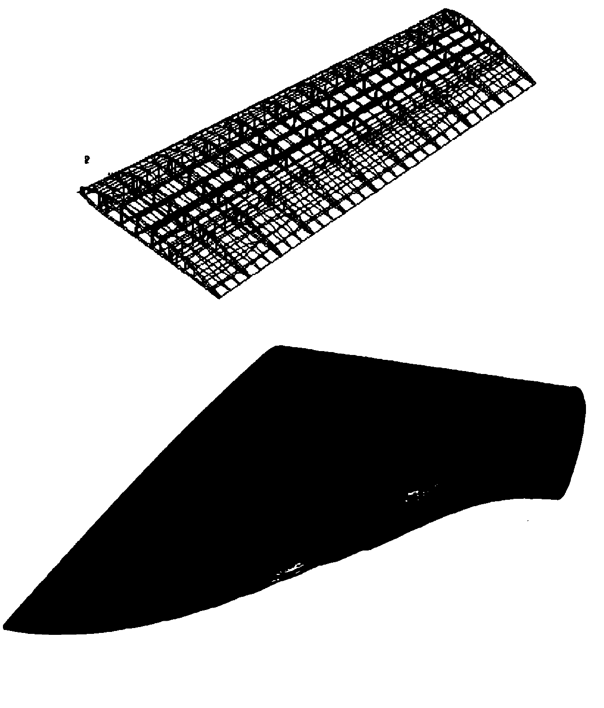
[0027] Then use the finite element analysis of the wing of the fixed-wing aircraft, such as image 3 shown. First, the wing is modeled to form a grid structure diagram of the aircraft structure, and then the cloud image of the finite element analysis of the aircraft wing during the simulated flight.

[0028] Through finite element analysis, it is clear that the front wall 2, spar 3, stiffener 4, joint 5, stringer 6, wing rib 7 and rear wall 8 are all stress-bearing supporting structures of the wi...

Embodiment 2

[0035]Taking the manufacture of smart prostheses as an example, smart prostheses are equipped with sensing devices such as multidimensional force sensors, Hall effect sensors, potentiometers, plantar pressure switches, and data acquisition chips. Among them, the multi-dimensional force sensor can detect and measure the ground reversal and moment of the three lines of defense. Real-time measurement of rigid body force / torque signals. The Hall sensor is easy to install, and the detection signal only has high and low level exchanges, which is easy to detect and use, and the walking speed can be calculated by the time when the detection level changes. The potentiometer acquires the joint angle at any time. The plantar pressure switch can detect the plantar pressure by itself and distinguish between support phase and swing phase.

[0036] In addition, an artificial rubber skin is installed on the outer cover of the prosthesis, and temperature, touch and humidity sensors are insta...


PUM

PropertyMeasurementUnit
thicknessaaaaaaaaaa
diameteraaaaaaaaaa

Abstract

The invention discloses a manufacturing method of a composite additional material. The manufacturing method of the composite additional material is invented aiming at the diversity of materials formedby multiple functionality of multi-functional multi-material structural model components. The manufacturing method of the composite additional material provided by the invention comprises the steps of firstly utilizing a structure design software for designing internal and external structures of a model, carrying out finite element analysis, defining the change situations of a component structureunder the physical actions such as stressing and heating, and designing material compositions and components of different stressing and heating structure parts; and secondly, by utilizing multiple additional material manufacturing methods and multiple materials, directly preparing some functional elements into a manufactured component in the manufactured structure components, so that high multifunctionality and a reliable structural performance of the manufactured component are realized.

Description

technical field [0001] The invention relates to a process of additive manufacturing, in particular to a method for preparing a multi-functional multi-material model component manufactured by composite additive. The composite additive manufacturing method belongs to the field of additive manufacturing. Background technique [0002] The additive manufacturing method is a high-tech manufacturing method developed in the late 1980s. It integrates computer-aided design and computer-aided manufacturing with the help of modern means such as computers, lasers, precision transmission and numerical control. According to the construction of three-dimensional models such as CAD or UG on the computer, the model is discretized into a series of orderly units according to certain rules, and the printing and forming system should automatically connect them to stand up after making some series of films to obtain a three-dimensional physical entity. [0003] From the development of the 1989s to...

Claims


Application Information

Patent Timeline
Patent Type & Authority Applications(China)
IPC IPC(8): B29C64/182B29C64/118B29C64/386B22F3/105B22F3/115B33Y10/00B33Y50/00B29L31/30
CPCB29C64/182B29C64/118B29C64/386B22F3/115B33Y10/00B33Y50/00B29L2031/3085B29L2031/7532B22F10/00B22F10/18B22F12/90B22F12/41B22F10/28B22F10/12B22F10/80Y02P10/25
Inventor 不公告发明人
Owner SHEN ZHEN QIANHAI SCICORE 3D TECH CO LTD
Why Eureka
Try Eureka