Converter bottom blowing process for grouped air blowing control of bottom blown bricks

A converter bottom blowing and air blowing control technology, applied in the direction of manufacturing converters, etc., can solve the problems of aggravating bottom blowing components, difficulty in ensuring bottom blowing effect, poor bottom blowing effect, etc., to avoid frequent changes, improve stirring effect, Easy-to-use effects

Active Publication Date: 2019-10-18
HANDAN IRON & STEEL GROUP +1
View PDF6 Cites 2 Cited by
  • Summary
  • Abstract
  • Description
  • Claims
  • Application Information

AI Technical Summary

Problems solved by technology

[0004] With the adjustment of domestic iron and steel production capacity, the number of large-scale converters tends to increase, and a large number of low-stirring intensity bottom-blowing designs are often used. Bottom-blown bricks are blown at the same time. After the converter has produced 2000-3000 furnaces, some bottom-blown components begin to block , and in order to pursue the furnace life of the converter, the operation of reducing the amount of bottom blowing gas in the later stage is often adopted, coupled with the reason of slag splashing, which further aggravates the blockage of the bottom blowing components, resulting in worse bottom blowing effect, and it is difficult to guarantee the effect of bottom blowing; on the contrary, In the paper "Science and Technology Progress of Converter Steelmaking under the Situation of Transformation and Development" (Steelmaking, Vol.33,1), Wang Xinhua and others pointed out that large-scale converters in Japan, South Korea and other countries are developing towards the direction of fewer bottom-blown bricks and higher stirring intensity. There is no slag splashing to protect the furnace, and the bottom blowing maintains a good effect within the economical furnace life of 5000-7000 furnaces

Method used


Image

  • Converter bottom blowing process for grouped air blowing control of bottom blown bricks
  • Converter bottom blowing process for grouped air blowing control of bottom blown bricks
  • Converter bottom blowing process for grouped air blowing control of bottom blown bricks

Examples


Embodiment Construction

[0031] The present invention is described in further detail below by specific embodiment:

[0032] This embodiment is described based on the 1 / 10 water simulation experiment results of a 260 ton converter.

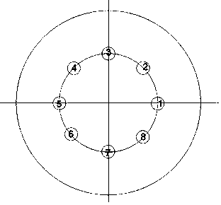
[0033] Under the actual production conditions of the converter, it is difficult to observe the bottom blowing flow field, and it is even more difficult to determine the reaction kinetics. As a method for studying the high-temperature solution reaction mechanism of steelmaking reaction vessels, hydraulic simulation has been regarded as a routine and reliable method. A 260-ton converter in a domestic steel plant uses 8 bottom blowing bricks. The bottom blowing bricks have a capillary structure and are evenly distributed on the 0.6R circumference of the converter bottom (R is the radius of the furnace bottom). 0.05 Nm 3 / t.min, 0.02 Nm 3 / t.min, 0.07Nm 3 / t.min, max. 0.15 Nm 3 / t.min, the top gun oxygen supply is 50000 Nm 3 / h, the typical height (gun position) from the ...


PUM


Abstract

The invention discloses a converter bottom blowing process for for grouped air blowing control of bottom blown bricks. The converter bottom blowing process includes the following two steps that firstly, bottom blown brick grouping is conducted, the bottom blown bricks located on the same circle are divided into two groups; and secondly, bottom blown brick grouped air volume control is carried out,in the converter production process, air volume control is carried out on the two groups of the bottom blown bricks, under the condition that the total air volume of bottom blowing remains unchanged,the ratio of the first group air volume to the second group air volume is 4:1-8:1 in the first furnace air volume opening mode of furnace service, the second group air volume guarantees that the bottom blowing brick process is not blocked, the second furnace air volume opening mode of furnace service is opposite to the first furnace air volume opening mode of furnace service, the ratio of the second group air volume to the first group air volume is 4:1-8:1, the first group air volume guarantees that the bottom blowing brick process is not blocked, and then heat is carried out alternately according to the first furnace air volume opening mode and the second furnace air volume opening mode. The flow of molten steel in a converter molten pool is accelerated, the reaction kinetics condition is improved, meanwhile the erosion of the bottom blown bricks is slowed down, the service life of the bottom blown bricks is prolonged, and the effect of bottom blowing is guaranteed while the furnaceage of a converter is prolonged.

Description

technical field [0001] The invention belongs to the technical field of steelmaking, and in particular relates to a converter bottom blowing process controlled by group blowing of bottom blowing bricks. Background technique [0002] Top-bottom combined blowing is a revolutionary technology of converter steelmaking technology. The use of converter bottom blowing strengthens the reaction kinetic conditions of molten steel in the converter and speeds up the reaction speed. Rapid dephosphorization has produced significant results. However, in order to increase the life of the furnace, the amount of bottom blowing gas is often reduced in the middle and late stages of the furnace operation. At the same time, the use of slag splashing protection technology causes the bottom blowing components to be often blocked in the middle and late stages, and its use is difficult to synchronize with the age of the furnace, which affects the , The actual use effect in the later stage. For this ...

Claims


Application Information

Patent Timeline
Patent Type & Authority Applications(China)
IPC IPC(8): C21C5/35
CPCC21C5/35
Inventor 颜慧成孙玉虎丁剑李建文潘树敏何顺生王现周
Owner HANDAN IRON & STEEL GROUP
Why Eureka
Try Eureka