Rotary target of magnetron sputtering coating machine

A magnetron sputtering and coating machine technology, applied in the field of rotating targets, can solve the problems of interference of magnet components, inability to form an effective loop, low support stability, etc., to avoid the influence of water flow, facilitate circulation and cooling, and facilitate use.

Active Publication Date: 2019-10-18
贵州商学院
View PDF3 Cites 2 Cited by
  • Summary
  • Abstract
  • Description
  • Claims
  • Application Information

AI Technical Summary

Problems solved by technology

[0003] However, the rotating target structure of the existing coating machine has some shortcomings in actual use. For example, when sputtering coating, the target will generate more heat, which needs to be cooled. If it is connected to the inside of the target, not only can no effective loop be formed, the heat exchange efficiency is low, and the cooling effect is poor, but it is also easy to cause interference effects on the magnet components. Install bearings for support, resulting in large outer diameter, low support stability, and unsatisfactory use effect

Method used

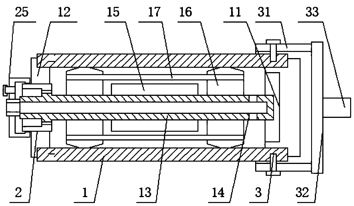
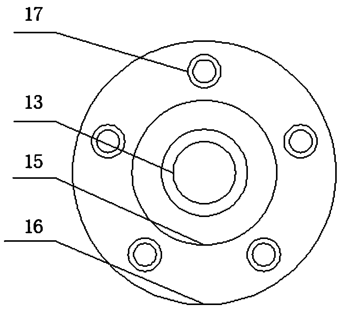
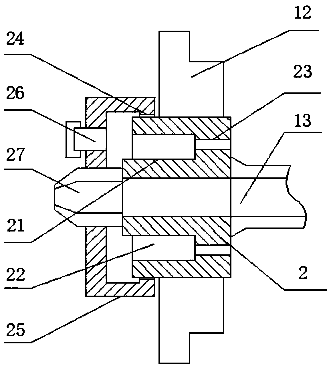

Image

  • Rotary target of magnetron sputtering coating machine
  • Rotary target of magnetron sputtering coating machine
  • Rotary target of magnetron sputtering coating machine

Examples


Embodiment Construction

[0031] The following will clearly and completely describe the technical solutions in the embodiments of the present invention in conjunction with the accompanying drawings in the embodiments of the present invention; obviously, the described embodiments are only part of the embodiments of the present invention, not all embodiments, based on The embodiments of the present invention and all other embodiments obtained by persons of ordinary skill in the art without making creative efforts belong to the protection scope of the present invention.

[0032] In the description of the present invention, it should be noted that the orientations or positional relationships indicated by the terms "upper", "lower", "inner", "outer", "top / bottom" etc. are based on the orientations shown in the drawings Or positional relationship is only for the convenience of describing the present invention and simplifying the description, but does not indicate or imply that the device or element referred t...


PUM


Abstract

The invention discloses a rotary target of a magnetron sputtering coating machine, and belongs to the field of coating machines. The rotary target of the magnetron sputtering coating machine comprisesa target material, a first cover plate is fixedly arranged on the surface of the back side of the target material, a second cover plate is fixedly arranged on the front side surface of the target material, a cooling pipe is fixedly arranged in the middle of the rear side surface of the second cover plate, a communication hole is formed in the rear end of the outer surface of the cooling pipe, a magnet ring is fixedly connected to the middle of the outer surface of the cooling pipe, sealing supporting plates are fixedly adhered to the two ends of the outer surface of the cooling pipe, the outer surface of the sealing supporting plate is slidably connected to the two ends of the inner side surface of the target material, a connecting pipe is fixedly inlaid in the inner surface of the sealing supporting plate, a connecting seat is fixedly connected to the center of the inner part of the second cover plate, an inner pipe is arranged in the connecting seat, so that the convenience and thestability of use can be greatly improved, and the safety and efficiency are ensured.

Description

technical field [0001] The invention relates to the field of coating machines, in particular to a rotating target of a magnetron sputtering coating machine. Background technique [0002] Vacuum evaporation coating, vacuum sputtering coating and vacuum ion coating have developed rapidly in the past ten years, and have become one of the most advanced surface treatment methods today. A film layer is formed on the surface of the workpiece, that is, the coating is achieved. [0003] However, the rotating target structure of the existing coating machine has some shortcomings in actual use. For example, when sputtering coating, the target will generate more heat, which needs to be cooled. If it is connected to the inside of the target, not only can no effective loop be formed, the heat exchange efficiency is low, and the cooling effect is poor, but it is also easy to cause interference effects on the magnet components. Bearings are installed for support, resulting in a large oute...

Claims


Application Information

Patent Timeline
Patent Type & Authority Applications(China)
IPC IPC(8): C23C14/35
CPCC23C14/35
Inventor 张俊
Owner 贵州商学院
Why Eureka
Try Eureka