Sponge urban road in which comprehensive pipe rack is designed and road construction method

A technology of sponge city and comprehensive pipe gallery, applied in the field of construction engineering, can solve the problems of poor anti-seepage ability of pipe gallery, achieve the effect of reducing rainwater leakage, reducing water storage requirements, and improving water storage utilization rate

Inactive Publication Date: 2019-10-18
CHINA CONSTR FIRST BUILDING GRP CORP LTD
View PDF7 Cites 2 Cited by
  • Summary
  • Abstract
  • Description
  • Claims
  • Application Information

AI Technical Summary

Problems solved by technology

[0007] The purpose of the present invention is to provide a road with a pipe gallery structure for the sponge city road, which can effectively improve the anti-seepage ability of the pipe gallery, in view of the problem of poor anti-seepage ability of the pipe gallery in the construction of the current sponge city road Construction method

Method used


Image

  • Sponge urban road in which comprehensive pipe rack is designed and road construction method
  • Sponge urban road in which comprehensive pipe rack is designed and road construction method
  • Sponge urban road in which comprehensive pipe rack is designed and road construction method

Examples


Embodiment 1

[0073] Example 1, such as Figure 1-5 Shown:

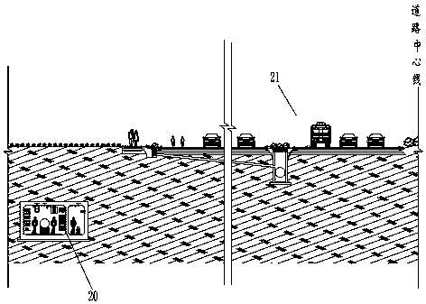
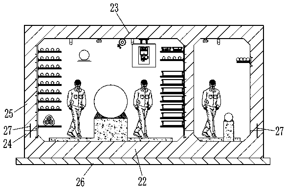
[0074] A sponge city road designed with a comprehensive pipe gallery, including a pipe gallery structure 20, the pipe gallery structure 20 includes a bottom plate 22, a side wall and a roof 23, and the side wall is vertically divided into an upper wall 25 located above and the lower wall 24 below the upper wall 25, the upper edge of the lower wall 24 is in contact with the lower edge of the upper wall 25, and the lower wall 24 is cast integrally with the bottom plate 22, so The upper wall body 25 and the top plate 23 are poured integrally.

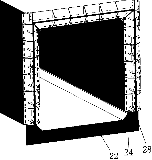
[0075] In the cast-in-place construction of the pipe gallery, the current usual method is: first pour the bottom plate 22 in the trench of the excavated pipe gallery, and after the bottom plate 22 is hardened, arrange the formwork bracket 29 and the side wall formwork on the bottom plate 22, and then carry out For the pouring construction of the side wall, after the side wall is hardened, se...

Embodiment 2

[0082] Example 2, such as Figure 1-7 Shown:

[0083] A sponge city road designed with a comprehensive pipe gallery. On the basis of Example 1, the sponge city road also includes a road structure 21, and the pipe gallery structure 20 is located on the side of the road structure 21, and is connected to the The road structure 21 is parallel, and the road structure 21 includes: a roadway 1 and a first green space structure 2 arranged on the side of the roadway 1, and the first green space structure 2 is along the roadway 1. Set in the length direction, the first green space structure 2 includes a first green space foundation pit 3 excavated in parallel along the roadway 1, on the bottom and side walls of the first green space foundation pit 3, there are paved to prevent water seepage The leaky first anti-seepage layer 4, the first green land foundation pit 3 above the first anti-seepage layer 4 is backfilled with planting soil 5, and the first anti-seepage layer 4 is close to th...

Embodiment 3

[0104] Example 3, such as Figure 1-7 Shown:

[0105] A sponge city road designed with a comprehensive pipe gallery. On the basis of Embodiment 2, the first green space structure 2 also includes a number of first overflow wells 15 arranged along the length direction of the first green space structure 2, The level of the wellhead of the first overflow well 15 is lower than or equal to the level of the upper edge of the first anti-seepage layer 4 , and the adjacent first overflow wells 15 are connected by setting a drainage pipe 19 . In the scheme of the present application, by setting the first overflow well 15, when the rainfall is large, when the rainwater collected in the first green space structure 2 exceeds the wellhead of the first overflow well 15, it enters the first overflow well 15 and then It is discharged by the drainpipe 19 to prevent the rainwater in the first green land from pouring back onto the road surface of the roadway 1.

[0106] As a preferred technical ...


PUM


Abstract

The invention relates to the technical field of constructional engineering, in particular to a sponge urban road in which a comprehensive pipe rack is designed and a road construction method. The sponge urban road comprises a pipe rack structure. The pipe rack structure comprises a bottom plate, a side wall and a top plate, wherein the side wall is divided into an upper wall body located at the upper position and a lower wall body located below the upper wall body in the vertical direction. The upper edge of the lower wall body is connected with the lower edge of the upper wall body. The lowerwall body and the bottom plate are integrally poured. The upper wall body and the top plate are integrally poured. By adoption of the technical scheme, firstly, convenient installation of a templatesupport and a pouring template is ensured, meanwhile, the seepage preventing capability of the pipe rack is further improved, and the pouring precision of the upper wall body is ensured.

Description

technical field [0001] The invention relates to the technical field of construction engineering, in particular to a sponge city road designed with a comprehensive pipe gallery and a road construction method. Background technique [0002] With the advancement of science and technology, urban ecological construction is increasingly concerned by the public, and sponge city is an important part of urban ecological construction. As far as sponge city is concerned, it is a new generation of urban stormwater management concept, which refers to the city's adaptation It has good resilience in terms of environmental changes and natural disasters caused by rainwater, and can also be called a water-elastic city. The international general term is: low-impact development rainwater system construction. Therefore, as mentioned above, the core function of the sponge city is to absorb, store, infiltrate, purify and utilize the stored water when it rains. [0003] In the current construction ...

Claims


Application Information

Patent Timeline
Patent Type & Authority Applications(China)
IPC IPC(8): E02D29/045E02D29/16E02D31/02E01C1/00E02D31/00E01C11/22E01C3/04E03F5/04E03F5/06A01G20/00
CPCE02D29/10E02D29/16E02D31/025E01C1/002E02D31/004E01C11/227E01C3/04E03F5/0401E03F5/06A01G20/00E02D2250/0007E02D2250/0023
Inventor 漆涛陈东川何煜民冯学松古川朱锐李萍周杰杨闯杨汉波谢全鸿刘燕
Owner CHINA CONSTR FIRST BUILDING GRP CORP LTD
Why Eureka
Try Eureka