Multilayer wall embedded with phase change filling material and provided with cavity

A filling material and phase change technology, which is applied in the field of building walls, can solve the problems of adverse effects on the production and use of building walls, the failure of phase change materials to achieve phase change cycle, and the complicated structure of mechanical devices, etc., and achieve good market application prospects , Improving indoor comfort and simple operation

Pending Publication Date: 2019-10-18
NANHUA UNIV
View PDF5 Cites 6 Cited by
  • Summary
  • Abstract
  • Description
  • Claims
  • Application Information

AI Technical Summary

Problems solved by technology

[0004] However, due to the above-mentioned combination of the existing phase change materials and building walls, due to the low temperature (winter) or high temperature (summer), the phase change material may not be able to achieve a complete phase change cycle throughout the day, so that its latent heat utilization The efficiency is not high; and the active st

Method used


Image

  • Multilayer wall embedded with phase change filling material and provided with cavity
  • Multilayer wall embedded with phase change filling material and provided with cavity
  • Multilayer wall embedded with phase change filling material and provided with cavity

Examples


Embodiment 1

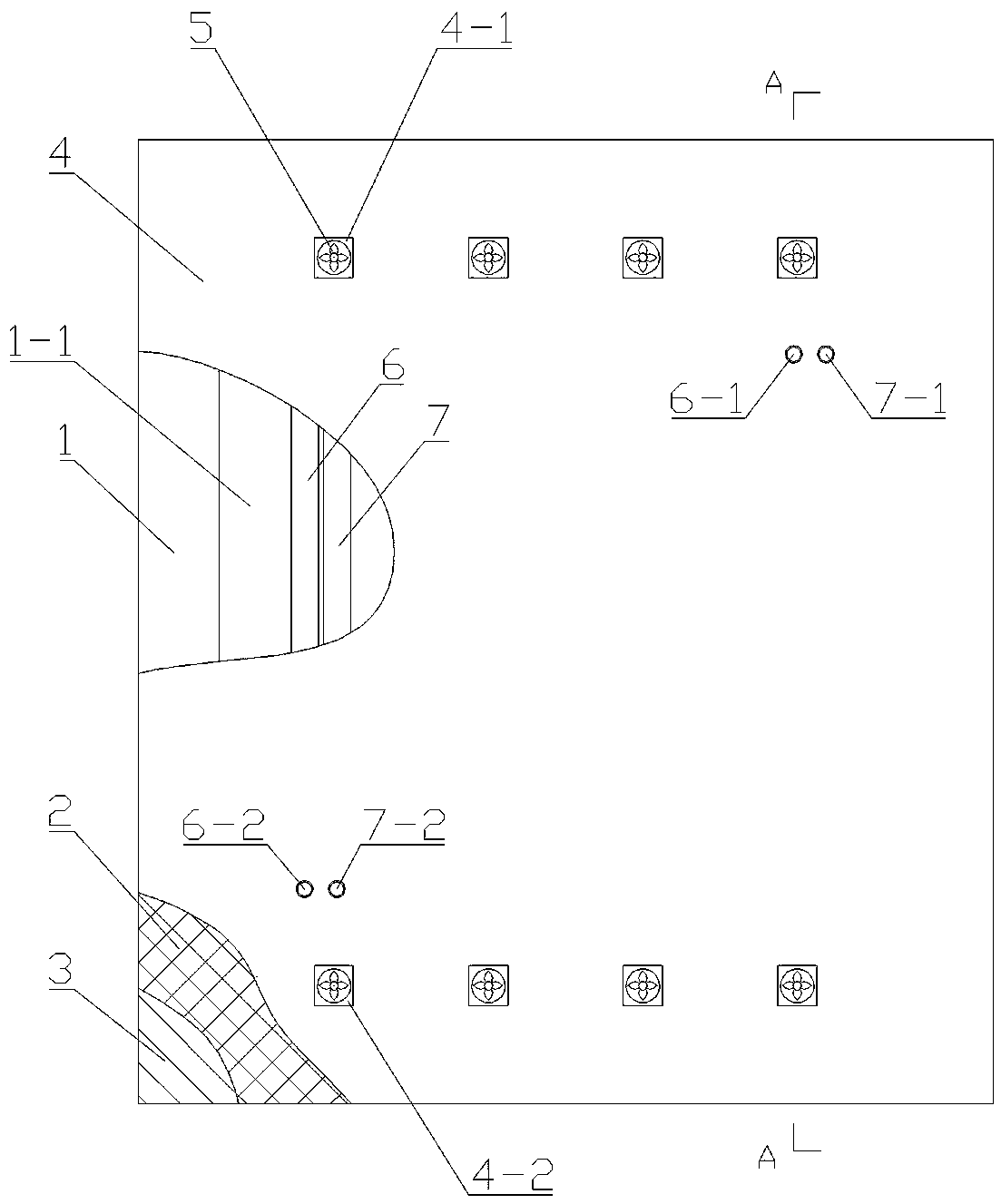
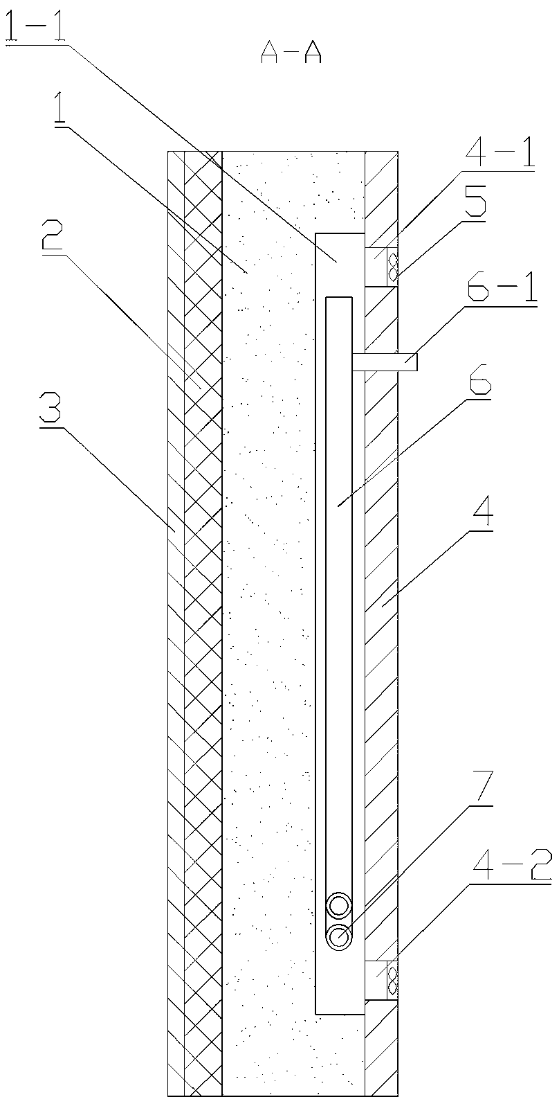
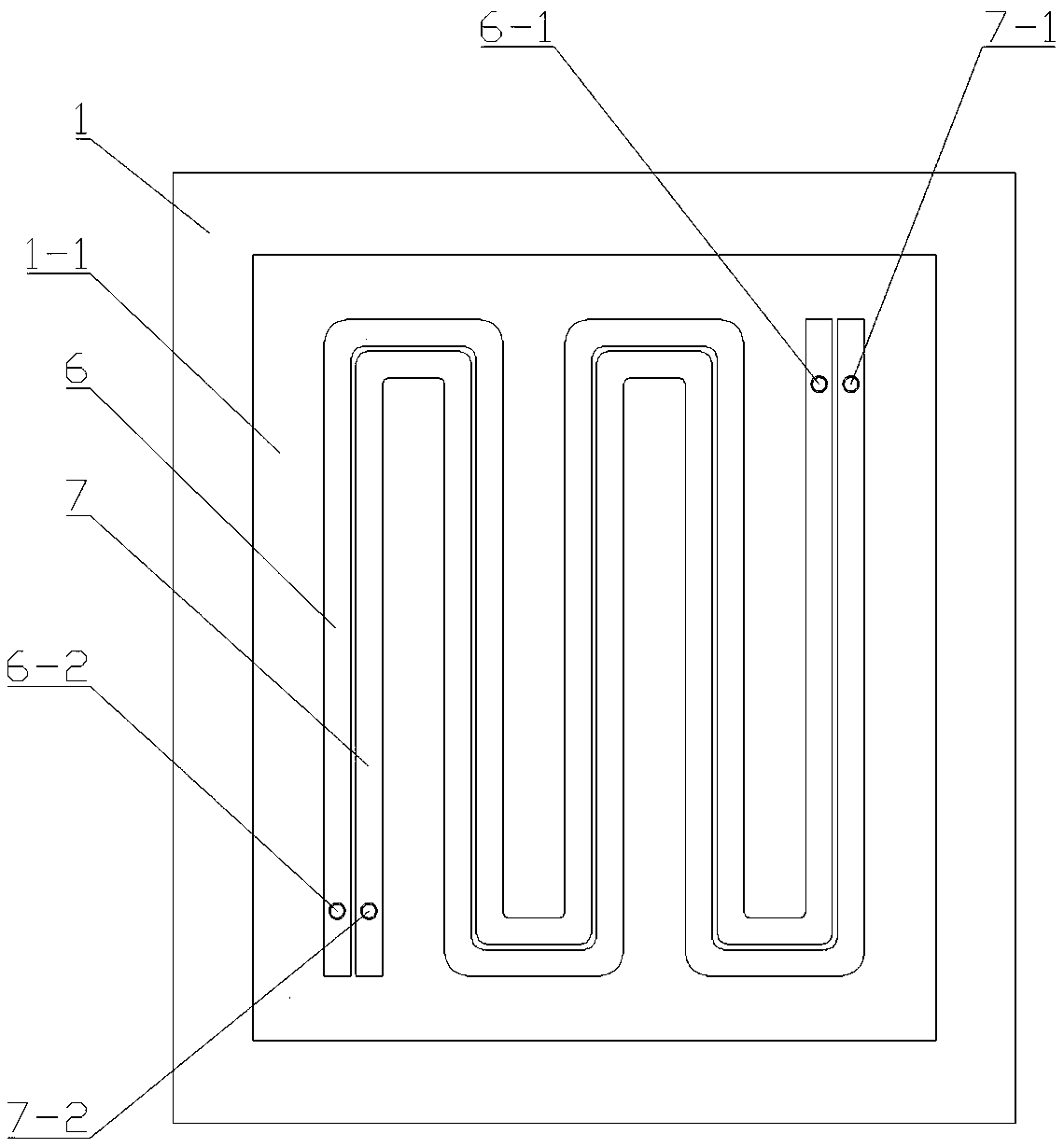
[0029] Embodiment one, such as Figure 1-4 As shown, the multi-layer wall with a cavity built-in phase change filling material includes concrete wall 1, insulation layer 2, reflection layer 3, finish layer 4, fan 5, high temperature phase change material water pipe 6 and low temperature phase change material Material water pipe7.

[0030] A cavity 1 - 1 is provided in the concrete wall 1 close to the finish layer 4 .

[0031] The thermal insulation layer 2 is arranged on the outside of the concrete wall 1 for thermal insulation of the concrete wall 1 .

[0032] The reflective layer 3 is arranged close to the outer side of the thermal insulation layer 2, and it is made of a high-reflectivity coating, which can resist part of the solar radiation and reduce the heat from the outside into the room.

[0033] The upper end of the facing layer 4 is provided with a plurality of upper air outlets 4-1, and the lower end is provided with a plurality of lower air outlets 4-2, each upper...


PUM

PropertyMeasurementUnit
Phase transition temperatureaaaaaaaaaa

Abstract

The invention discloses a multilayer wall embedded with a phase change filling material and provided with a cavity. The multilayer wall comprises a concrete wall, a thermal insulating layer, a reflecting layer, a facing layer, a draught fan, a high temperature phase change material water pipe and a low temperature phase change material water pipe, wherein the cavity is formed in the concrete wall;the thermal insulating layer and the reflecting layer are sequentially arranged on the outer side of the concrete wall; an upper tuyere and a lower tuyere communicating with the cavity are formed inthe two ends of the facing layer; the high temperature phase change material water pipe and the low temperature phase change material water pipe are arranged in the cavity; each of the high temperature phase change material water pipe and the low temperature phase change material water pipe comprises a concentric pipe, a water inlet pipe and a water outlet pipe; the concentric pipe comprises an outer pipe, an inner pipe, a circular ring passage and a temperature sensor; and the circular ring passage with the two ends sealed is filled with the phase change filling material. The phase change filling material is controlled to absorb and release heat at daytime and night of different seasons to adjust the temperature of the indoor air. The multilayer wall is simple in structure and convenientand fast to operate, can effectively alleviate the fluctuation of the indoor temperature to improve the indoor comfort level and realizes the purpose of building energy conservation all year round.

Description

technical field [0001] The invention relates to a building wall, in particular to a multi-layer wall with a cavity and a built-in phase change filling material. Background technique [0002] With the rapid development of global industry, the supply of non-renewable energy represented by coal, oil and natural gas has shown an increasingly tense trend. How to realize energy conservation and emission reduction has become a arduous and urgent task before mankind. About 80% of building energy consumption is for ventilation, heating and air conditioning. In the current situation of energy shortage, how to improve energy efficiency in buildings and minimize building energy consumption is of great significance to energy conservation. [0003] Phase change material (PCM) has strong latent heat storage characteristics. Combining it with building walls can use its own phase change to store temporarily unused energy and release it when needed, alleviating indoor temperature fluctuatio...

Claims


Application Information

Patent Timeline
IPC IPC(8): E04B2/00E04B1/74E04B1/76F24F5/00
CPCE04B1/74E04B1/762E04B2/00E04B2001/7691F24F5/0021F24F2221/17Y02E60/14
Inventor 谢东巫洋茜王汉青何宗武
Owner NANHUA UNIV
Why Eureka
Try Eureka