Multi-unit system

A multi-line system and compressor technology, applied in the field of multi-line systems, can solve the problems of compressor burnout, high return air temperature and high exhaust temperature, and achieve the effects of ensuring comfort, reducing area and increasing area

Inactive Publication Date: 2014-12-03
GUANGDONG CHIGO HEATING & VENTILATION EQUIP CO LTD
View PDF4 Cites 6 Cited by
  • Summary
  • Abstract
  • Description
  • Claims
  • Application Information

AI Technical Summary

Problems solved by technology

In low-temperature cooling, all the air-cooled heat exchangers of the outdoor unit are used as condensers, which may cause the condensation effect to be too good, and the evaporator cannot be completely evaporated, which will cause the system to return to liquid refrigerant, and in severe cases, the compressor will burn out; When heating, the exhaust temperature of the compressor is high, and the system pressure will also be high at this time, and the air-cooled heat exchanger of the outdoor unit is used as an evaporator, and the evaporation effect is too good, resulting in high return air temperature and high return air temperature. If the air-cooled heat exchanger of the outdoor unit is used as the evaporator for low-temperature heating, the air-cooled heat exchanger of the outdoor unit is used as a condenser, and the heat exchange of the indoor unit The high-temperature and high-pressure refrigerant melts the frost when the air-cooled heat exchanger of the outdoor unit is condensed. However, the condensed refrigerant needs to evaporate and absorb heat in the heat exchanger of the indoor unit. In this way, if the indoor unit blows air, it will blow out It will be cold air, even if the indoor unit is not blown, it cannot continue to heat, resulting in the multi-connected system cannot continue to provide heating demand, thus affecting the user's comfort requirements

Method used


Image

  • Multi-unit system

Examples


Embodiment Construction

[0035] In order to make the purpose, features and advantages of the present invention more obvious and understandable, the technical solutions protected by the present invention will be clearly and completely described below using specific embodiments and accompanying drawings. Obviously, the implementation described below Examples are only some embodiments of the present invention, but not all embodiments. Based on the embodiments in this patent, all other embodiments obtained by persons of ordinary skill in the art without creative efforts fall within the protection scope of this patent.

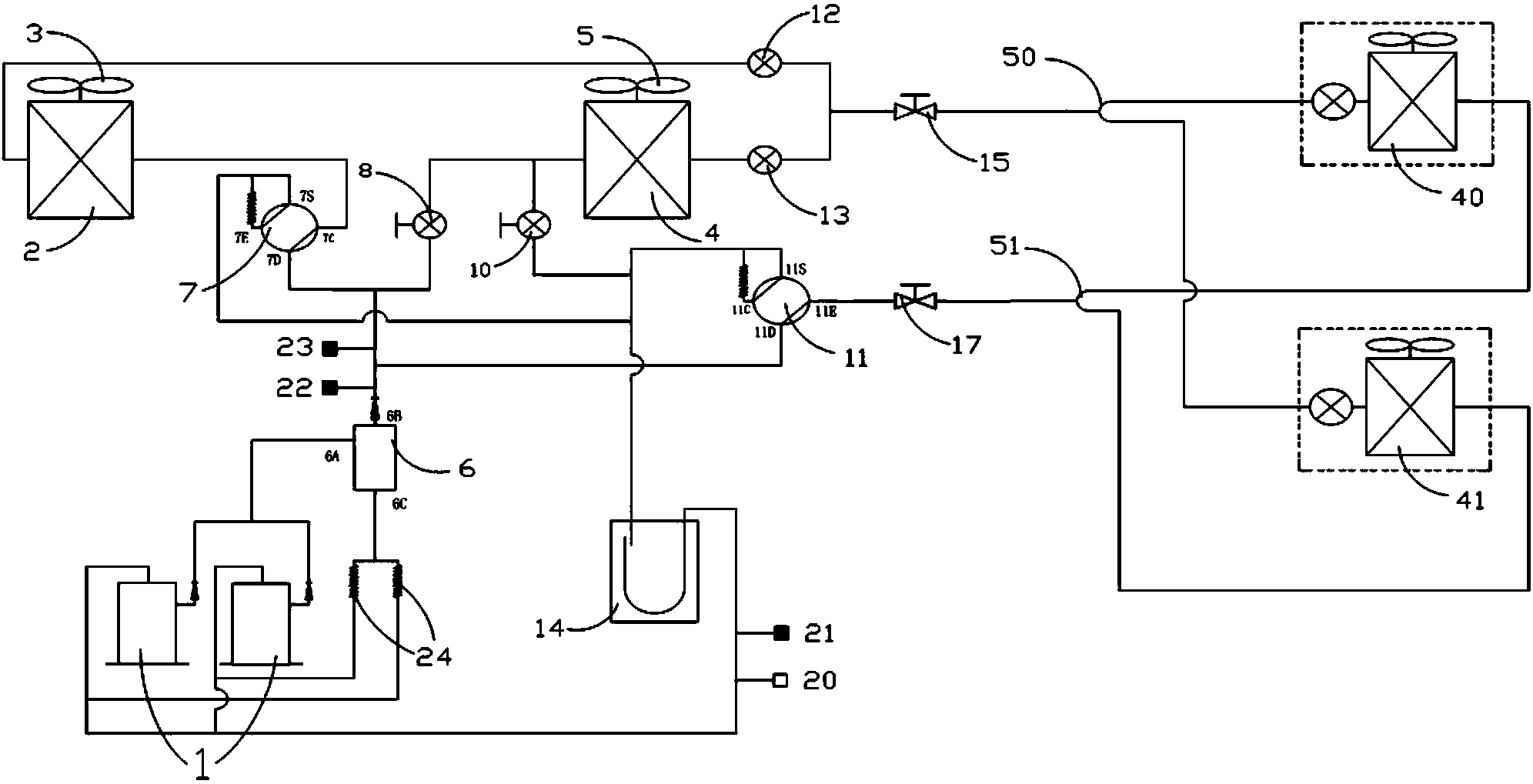
[0036] see figure 1 As shown, this embodiment discloses a schematic structural diagram of a multi-line system, the multi-line system includes: a compressor for supplying refrigerant to the system, and a first air-cooled heat exchanger used as an evaporator or condenser 2 and the first outdoor fan 3 used to enhance heat exchange for the first air-cooled heat exchanger 2, the second air-coo...


PUM


Abstract

The invention discloses a multi-unit system. By replacing an original single air cooling heat exchanger with two air cooling heat exchangers, during low-temperature refrigeration, the multi-unit system can achieve the aim of the area of an air cooling condenser by powering off one of the air cooling heat exchangers, or reduce the area of the air cooling condenser, enlarge the area of an air cooling evaporator and reduce the risk of liquid-state refrigerant returning of the system by taking one of the air cooling heat exchangers as the condenser and the other air cooling heat exchanger as an evaporator; during high-temperature heating, the multi-unit system can take one of the air cooling heat exchangers as the evaporator and the other air cooling heat exchanger as the condenser to control and maintain system pressure and air return temperature within a reasonable range; during low-temperature heating and when the air cooling heat exchanger of an outdoor unit needs defrosting, the multi-unit system performs defrosting by taking one of the air cooling heat exchangers as the condenser and continues to perform heating by taking the other air cooling heat exchanger as the evaporator. Therefore, the requirements of units on continuous heat supply can be met, and further the comfort level of users can be guaranteed.

Description

technical field [0001] The present invention relates to the technical field of air conditioning, and more specifically, relates to a multi-connected system. Background technique [0002] In the existing multi-connected system, the air-cooled heat exchangers of the outdoor units are either used as evaporators or used as condensers. In low-temperature cooling, all the air-cooled heat exchangers of the outdoor unit are used as condensers, which may cause the condensation effect to be too good, and the evaporator cannot be completely evaporated, which will cause the system to return to liquid refrigerant, and in severe cases, the compressor will burn out; When heating, the exhaust temperature of the compressor is high, and the system pressure will also be high at this time, and the air-cooled heat exchanger of the outdoor unit is used as an evaporator, and the evaporation effect is too good, resulting in high return air temperature and high return air temperature. If the air-co...

Claims


Application Information

Patent Timeline
IPC IPC(8): F25B29/00F25B13/00F25B41/04F25B41/06F25B41/20F25B41/34
Inventor 刘红斌王峰
Owner GUANGDONG CHIGO HEATING & VENTILATION EQUIP CO LTD
Why Eureka
Try Eureka