A multipurpose door device
What is Al technical title?
Al technical title is built by PatSnap Al team. It summarizes the technical point description of the patent document.
A door device and door panel technology, which can be applied to service doors, door leaves, and pass-through doors, etc., can solve problems such as reducing the utilization rate of indoor effective space, and achieve the effects of improving efficient control capability, improving stability, and improving diversity.
Active Publication Date: 2021-01-12
SUZHOU XINYAO HEALTH TECH CO LTD
View PDF6 Cites 0 Cited by
Summary
Abstract
Description
Claims
Application Information
AI Technical Summary
This helps you quickly interpret patents by identifying the three key elements:
Problems solved by technology
Method used
Benefits of technology
Problems solved by technology
[0002] Doors are one of the essential furniture in family life. Doors can be divided into exterior doors and interior doors. Exterior doors are mainly used for security maintenance such as anti-theft, and interior doors are mainly used for isolation. Modern social housing pressure is high, and small-sized houses Extremely popular, small-sized houses put forward higher requirements for indoor basic implementation, such as indoor doors can be retracted freely, increasing the passing area of aisles, to meet the needs of users in different environments, and to improve indoor air quality , the existing interior can only be realized by opening the door or installing additional gauze and other equipment, and at present many families keep pets, and in order to prevent pets from destroying indoor furniture, additional pet fence doors need to be purchased, which will reduce the effective indoor space at the same time utilization, this device effectively solves this problem
Method used
Image
Click on the blue label to locate the original text in one second.
Reading with bidirectional positioning of images and text.
Examples
Embodiment Construction
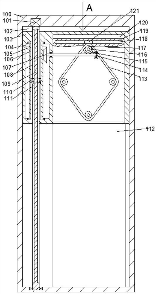
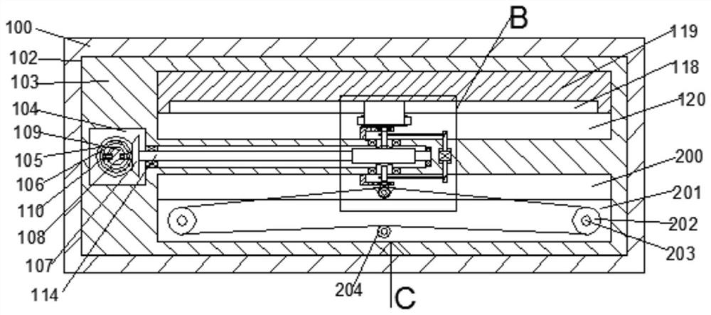
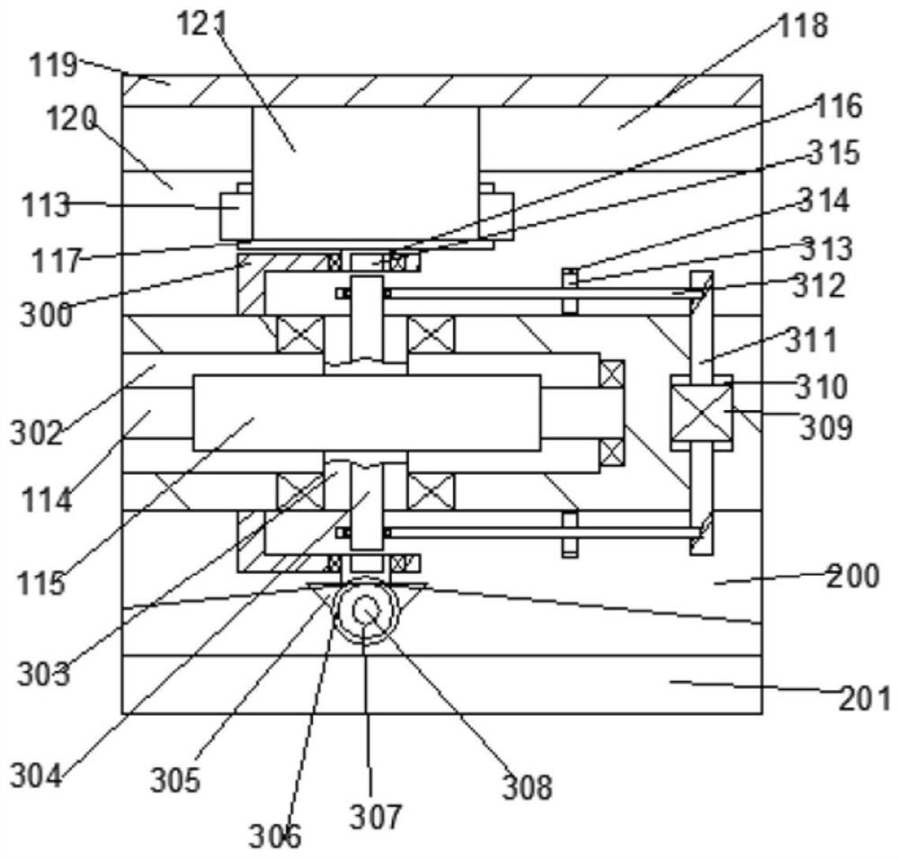
[0018] Combine below Figure 1-5 The present invention is described in detail, and for convenience of description, the orientations mentioned below are now stipulated as follows: figure 1 The up, down, left, right, front and back directions of the projection relationship itself are the same.
[0019] refer to Figure 1-5 , a multi-purpose door device according to an embodiment of the present invention, comprising a moving chamber 102 fixed in the wall body 100, and a channel 112 passing through the front and back is provided in the moving chamber 102, sliding with the left and right end walls of the moving chamber 102 A door 103 is provided, the door 103 is provided with a rotating chamber 104, and the rotating chamber 104 is provided with a rotating assembly, the rotating assembly drives the door 103 to move down to a designated position, and at the same time transmits the motion to the power assembly, so The right end wall of the rotating chamber 104 is provided with a doo...
PUM
Abstract
The invention discloses a multipurpose door device. A moving cavity fixedly arranged in a wall is included, a channel which is through front and back is arranged in the moving cavity, a door is arranged on the left and right end walls of the moving cavity in a sliding manner, a rotating cavity is formed in the door, a rotating assembly is arranged in the rotating cavity, the rotating assembly drives the door to move downwards to the designated position, and meanwhile, motion is transmitted to a power assembly. The device is simple in structure and convenient to operate. Through the rotating assembly, up and down moving of the door is adjusted, power control over an interior door is achieved, efficient control capacity of the device is improved, through the power assembly and a connecting assembly, power is selectively connected with a designated device, diversity of the device is improved, finally, through a switchable motion mechanism, flexible control of the door can be achieved, thework range of the device is widened, the efficiency is improved, the device reliability is improved, and the device is compact in structure, flexible, adjustable, and wide in application range.
Description
technical field [0001] The invention relates to the technical field of doors, in particular to a multi-purpose door device. Background technique [0002] Doors are one of the essential furniture in family life. Doors can be divided into exterior doors and interior doors. Exterior doors are mainly used for security maintenance such as anti-theft, while interior doors are mainly used for isolation. Modern social housing pressure is high, and small-sized houses Very popular, small-sized houses put forward higher requirements for indoor basic implementation, such as indoor doors can be retracted freely, increasing the passing area of aisles, to meet the needs of users in different environments, and to improve indoor air quality , the existing interior can only be realized by opening the door or installing additional gauze and other equipment, and at present many families keep pets, and in order to prevent pets from destroying indoor furniture, additional pet fence doors need t...
Claims
Application Information
Patent Timeline
Application Date:The date an application was filed.
Publication Date:The date a patent or application was officially published.
First Publication Date:The earliest publication date of a patent with the same application number.
Issue Date:Publication date of the patent grant document.
PCT Entry Date:The Entry date of PCT National Phase.
Estimated Expiry Date:The statutory expiry date of a patent right according to the Patent Law, and it is the longest term of protection that the patent right can achieve without the termination of the patent right due to other reasons(Term extension factor has been taken into account ).
Invalid Date:Actual expiry date is based on effective date or publication date of legal transaction data of invalid patent.