
System and method for scanning and detecting tiny scratch defects of panel

A technology for scratch defect and scanning detection, which is applied in the direction of optical testing of flaws/defects, measuring devices, and material analysis through optical means, and can solve the problems of subtle scratches and background confusion, small mirror reflection angles, and indistinguishability, etc. Achieve fast dynamic surface detection, do not affect the production speed, and achieve the effect of fast detection speed

Active Publication Date: 2019-10-18
UNIV OF SCI & TECH BEIJING
View PDF8 Cites 2 Cited by
  • Summary
  • Abstract
  • Description
  • Claims
  • Application Information

AI Technical Summary

Problems solved by technology

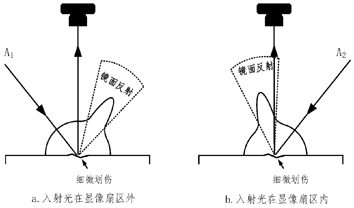
[0005] 2) The specular reflection angle of fine scratches is small and the direction is random. Existing machine vision inspection equipment usually adopts lighting systems with limited directions such as bright field and dark field lighting. The lighting direction cannot cover the "imaging sectors" of different scratches. "; while the dome light source omnidirectional lighting system has a blurring effect similar to that of the shadowless lamp, and it is difficult to distinguish between subtle scratches and background confusion
[0006] 3) For panel products with a certain curved surface, a single-directional light source is prone to produce high-light spots on the curved surface, which interferes with defect detection
The patent application number CN201210292335 uses two strip light sources to scan tiny defects on the metal plane, which improves the imaging quality of horizontal defects, but is not sensitive to vertical defects; the patent application number CN201810099920 uses multiple directional light sources to illuminate in turn, for Measuring the surface roughness of static flat objects is not convenient for fast dynamic detection of panel products on the assembly line

Method used


Image

  • System and method for scanning and detecting tiny scratch defects of panel
  • System and method for scanning and detecting tiny scratch defects of panel
  • System and method for scanning and detecting tiny scratch defects of panel

Examples


Embodiment Construction

[0030] In order to make the technical problems, technical solutions and advantages to be solved by the present invention clearer, the following will describe in detail with reference to the drawings and specific embodiments.

[0031] The invention provides a scanning detection system and method for fine scratch defects on a panel.

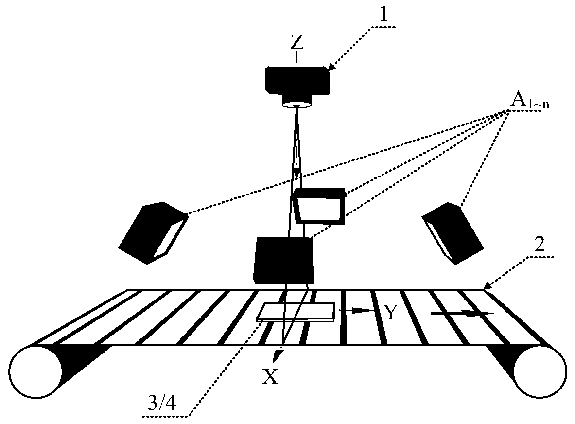
[0032] Such as figure 1 As shown, the system includes a multi-spectral line scan camera 1, a light source array A i and the transmission mechanism 2, the multispectral line scan camera 1 is located above the transmission mechanism 2, and the scanning line of the multispectral line scan camera 1 is perpendicular to the movement direction of the transmission mechanism 2, and the light source array A i It is located between the multi-spectral line scan camera 1 and the transmission mechanism 2, on which the panel 3 to be tested is placed.

[0033] In practical application, the panel under test is placed on the transmission mechanism; the multi-spect...


PUM


Abstract

The invention provides a scanning detection system and method for tiny scratch defects of a panel, and belongs to the technical field of surface defect detection. The system comprises a multi-spectral-line scanning camera, a light source array and a conveying mechanism; the multi-spectral-line scanning camera is located above the conveying mechanism, scanning lines are perpendicular to the conveying mechanism, and the light source array is located between the multi-spectral-line scanning camera and the conveying mechanism. According to the method, illumination light sources in multiple directions are adopted to cover imaging sectors with tiny scratch defects, so that the tiny scratch defects with sub-pixel sizes are clearly imaged; the multi-spectral-line scanning camera is adopted for scanning and imaging, and dynamic detection is achieved; a detection algorithm eliminates the influence of mirror surface light spots, and the method is suitable for scratch detection of the panel with acurved surface.

Description

technical field [0001] The invention relates to the technical field of surface defect detection, in particular to a scanning detection system and method for fine scratch defects on a panel. Background technique [0002] Products such as mobile phone casings have high requirements on the quality of the panel, and the surface of the panel made of aluminum, stainless steel, plastic, etc. is easily scratched by hard objects to produce subtle scratch defects. Scratch defects are small in width, the smallest reaches the micron scale, and can only be visualized under a specific light angle. Therefore, the quality inspection measures of manual naked eye observation are low in quality inspection efficiency, high in labor costs, and prone to missed inspections. [0003] The automatic surface inspection technology based on machine vision is widely used in the surface quality inspection of panel products, but there are problems in the detection of fine scratch defects: [0004] 1) The ...

Claims


Application Information

Patent Timeline
Patent Type & Authority Applications(China)
IPC IPC(8): G01N21/01G01N21/88
CPCG01N21/01G01N21/88
Inventor 周鹏徐科王磊杨朝霖
Owner UNIV OF SCI & TECH BEIJING
Learn More