A method of protecting electronic components in a single crystal silicon differential pressure transmitter using resistance changes

A technology of differential pressure transmitter and resistance change, applied in the direction of electrical component structure association, etc., can solve problems such as open circuit, damaged electronic components, circuit open circuit, etc., to avoid damage and ensure the effect of service life

Active Publication Date: 2020-06-30
诺特达新材料科技(上海)有限公司
View PDF10 Cites 0 Cited by
  • Summary
  • Abstract
  • Description
  • Claims
  • Application Information

AI Technical Summary

Problems solved by technology

[0002] The single crystal silicon differential pressure transmitter is used to measure the liquid level of the liquid, the density of the gas or the pressure of the steam, and then convert it into a current signal output, but there are a large number of electronic components inside the existing pressure sensor cover, some of which are The joints between the components are welded together by tin, and the melting point of tin is only 231.93 degrees Celsius, but in the case of high temperature, if the staff is measuring the water vapor pressure, the temperature of the water vapor can reach up to 384 degrees Celsius, if the surveyor does not pay attention to the measurement time, the measurement time is too long, the metal tin will slowly melt, there may be faults such as open circuit and open circuit between the circuits, and the electronic components may be damaged

Method used


Image

  • A method of protecting electronic components in a single crystal silicon differential pressure transmitter using resistance changes
  • A method of protecting electronic components in a single crystal silicon differential pressure transmitter using resistance changes
  • A method of protecting electronic components in a single crystal silicon differential pressure transmitter using resistance changes

Examples


Embodiment Construction

[0021] The following will clearly and completely describe the technical solutions in the embodiments of the present invention with reference to the accompanying drawings in the embodiments of the present invention. Obviously, the described embodiments are only some, not all, embodiments of the present invention. Based on the embodiments of the present invention, all other embodiments obtained by persons of ordinary skill in the art without making creative efforts belong to the protection scope of the present invention.

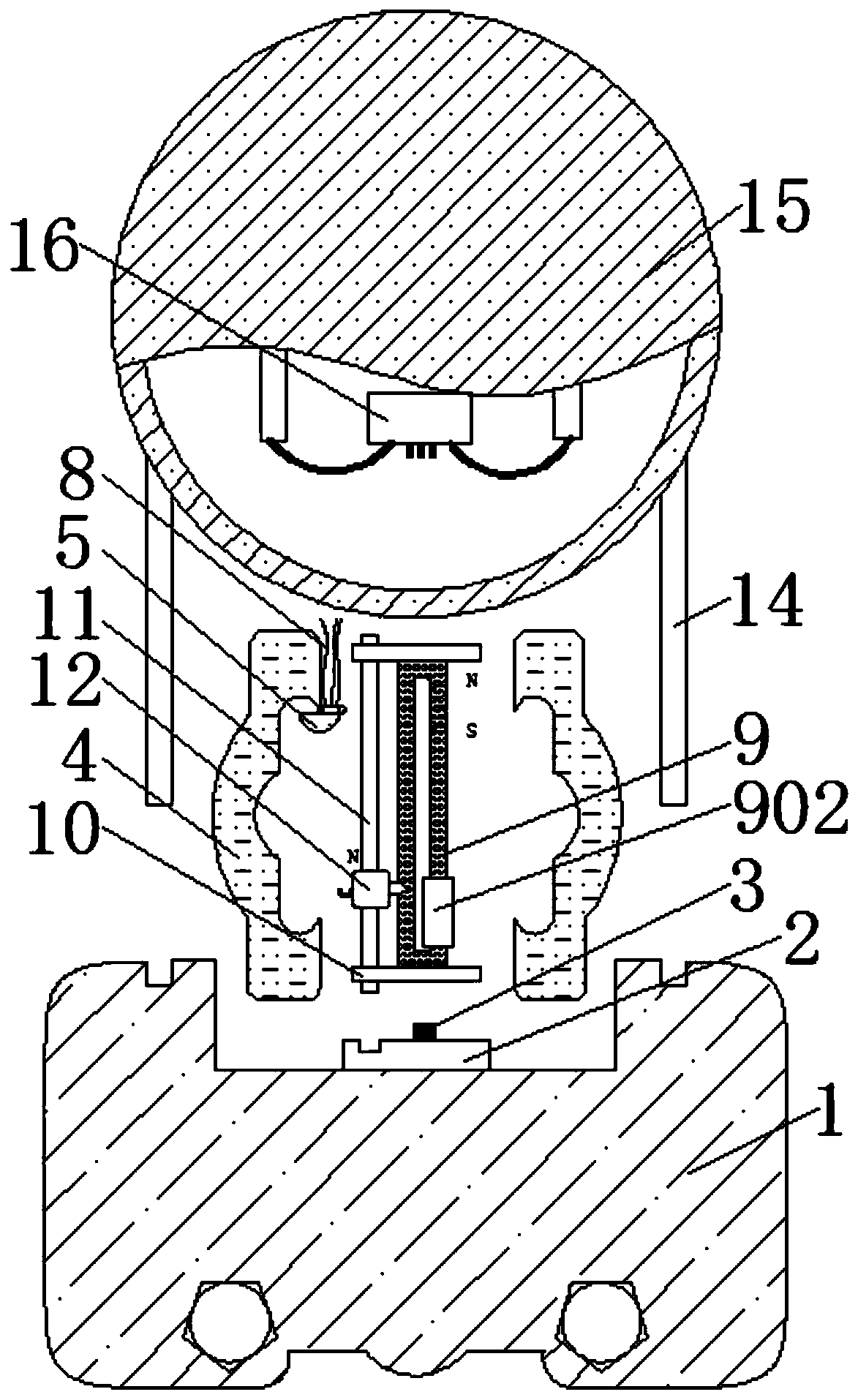
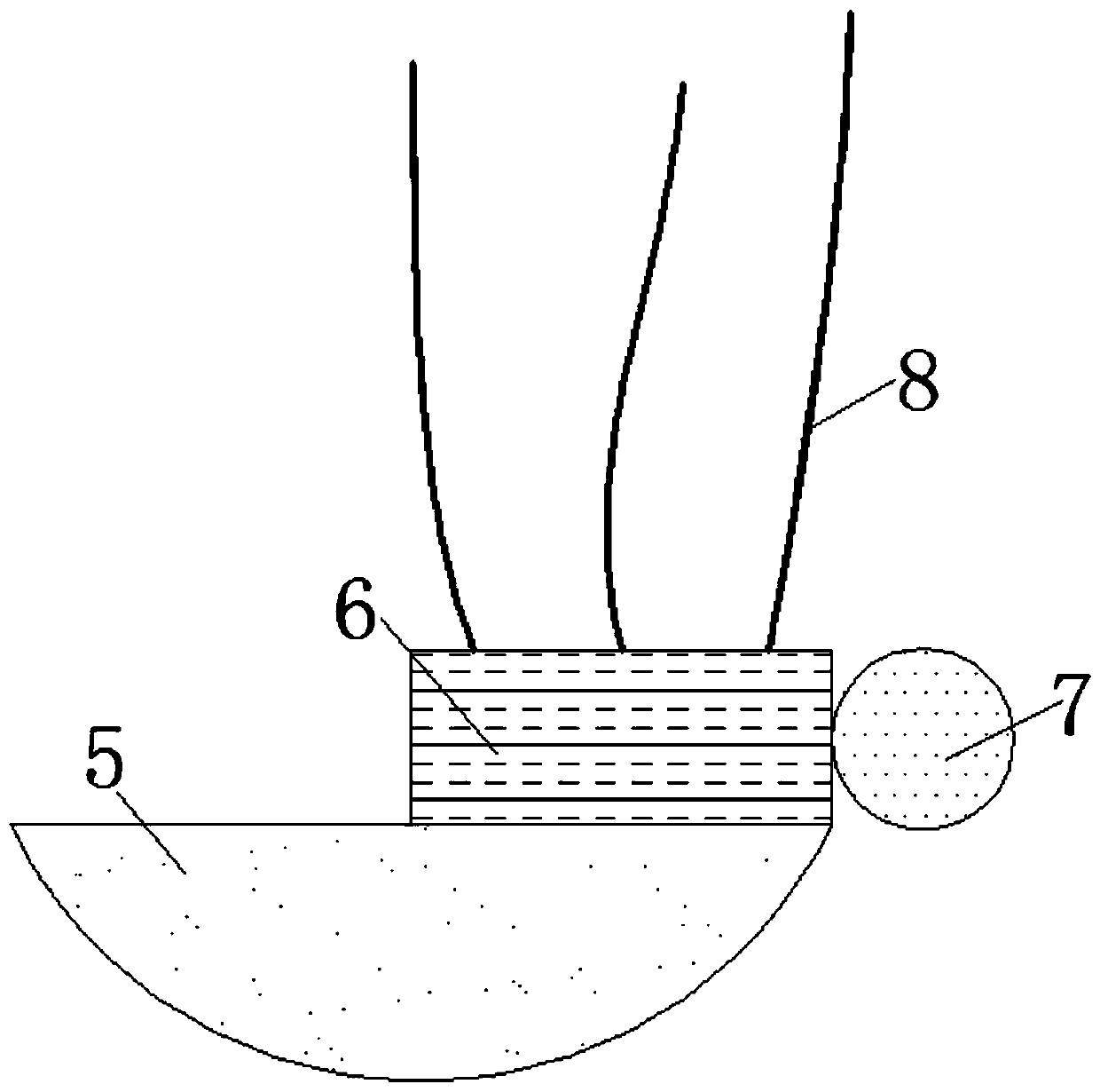
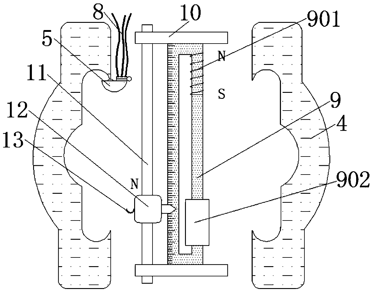
[0022] see Figure 1-4 :

[0023] A device for protecting electronic components in a single crystal silicon differential pressure transmitter by using resistance changes, including a splint 1, a mounting block 4 and a cover body 15, a connection block 2 is fixedly installed on the groove on the upper surface of the splint 1, and the connection block 2 A contact 3 is fixedly installed on the upper surface of the upper surface; the contact 3 is located in the m...


PUM


Abstract

The invention provides a method for protecting an electronic component in a monocrystalline silicon differential pressure transmitter by resistance change. The electronic component comprises a clamp plate, a mounting block and a cover body. A connecting block is fixedly mounted in the groove on the upper surface of the clamp plate. The upper surface of the connecting block is fixedly provided witha contact point. A contact block is fixedly mounted inside the left side of the mounting block. A guide block is overlapped on the upper surface of the right side of the contact block. The right endof the guide block is fixedly provided with a fixed ball. A lead is fixedly connected on the upper surface of the guide block. A metal rod is inserted in the middle part of the mounting block. A coilis fixedly connected on the upper end of the right side of the metal rod. A thermistor is fixedly mounted on the lower end of the right side of the metal rod. The guide block and the contact block canbe conveniently and effectively separated to form an open circuit through the cooperation of the guide block, the fixed ball, the lead and the arc plate, the brightness of the display screen is reduced, the working personnel are effectively reminded that the device is placed for too long and thus the service life of the electronic component can be guaranteed.

Description

technical field [0001] The invention relates to the technical field of new material manufacturing, in particular to an electronic component in a single crystal silicon differential pressure transmitter protected by resistance change. Background technique [0002] The single crystal silicon differential pressure transmitter is used to measure the liquid level of the liquid, the density of the gas or the pressure of the steam, and then convert it into a current signal output, but there are a large number of electronic components inside the existing pressure sensor cover, some of which are The joints between the components are welded together by tin, and the melting point of tin is only 231.93 degrees Celsius, but in the case of high temperature, if the staff is measuring the water vapor pressure, the temperature of the water vapor can reach up to 384 degrees Celsius, if the surveyor does not pay attention to the measurement time, the measurement time is too long, the metal tin...

Claims


Application Information

Patent Timeline
Patent Type & Authority Patents(China)
IPC IPC(8): H01F27/40
CPCH01F27/40
Inventor 徐梦姣熊烽刘爱莲
Owner 诺特达新材料科技(上海)有限公司
Why Eureka
Try Eureka