Preparation method of semiconductor device and prepared semiconductor device

A semiconductor and device technology, applied in the field of semiconductor device preparation and prepared semiconductor devices, can solve the problems of high leakage current, high power consumption, unsatisfactory, etc., and achieve the effect of reducing EOT

Active Publication Date: 2019-10-18
INST OF MICROELECTRONICS CHINESE ACAD OF SCI
View PDF7 Cites 0 Cited by
  • Summary
  • Abstract
  • Description
  • Claims
  • Application Information

AI Technical Summary

Problems solved by technology
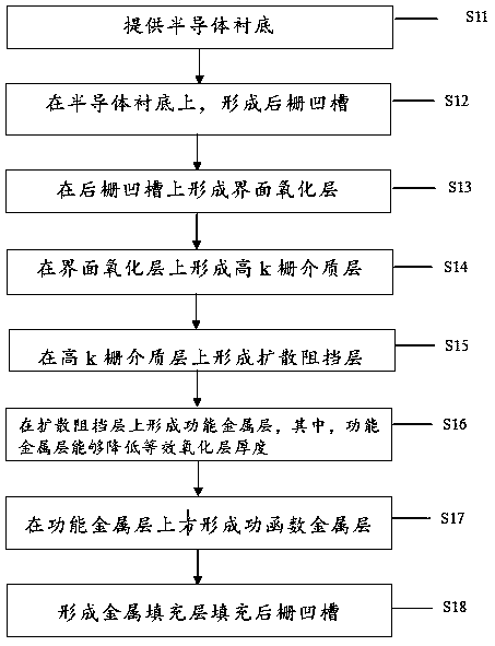
For SiO with less than 1nm 2 , cannot meet the needs of the technology due to unacceptably high leakage current and high power consumption due to the significant direct tunneling effect

Method used


Image

  • Preparation method of semiconductor device and prepared semiconductor device
  • Preparation method of semiconductor device and prepared semiconductor device
  • Preparation method of semiconductor device and prepared semiconductor device

Examples


Embodiment Construction

[0025] The following disclosure provides a number of different embodiments or examples for implementing different features of the invention. Specific examples of components and arrangements are described below to simplify the present disclosure. Of course, these are only examples and are not intended to limit the invention. For example, in the following description, forming a first component over or on a second component may include embodiments in which the first component and the second component are in direct contact, and may include additional components formed between the first component and the second component An embodiment such that the first part and the second part are not in direct contact.

[0026] In addition, for the convenience of description, spatial relationship terms such as "below", "beneath", "lower", "above", "upper" may be used herein to describe The relationship of one element or component to another element or component is shown. Spatially relative te...


PUM

PropertyMeasurementUnit
thicknessaaaaaaaaaa
thicknessaaaaaaaaaa
thicknessaaaaaaaaaa

Abstract

The invention provides a preparation method of a semiconductor device and the prepared semiconductor device. The method comprises the steps: providing a semiconductor substrate; forming a rear gate groove on the semiconductor substrate; forming an interface oxide layer on the rear gate groove; forming a high-k gate dielectric layer on the interface oxide layer; forming a diffusion barrier layer onthe high-k gate dielectric layer; forming a functional metal layer on the diffusion barrier layer, wherein the functional metal layer can reduce the equivalent oxide layer thickness; forming a work function metal layer on the functional metal layer; and forming a metal filling layer to fill in the rear gate groove. According to the method for reducing the EOT, the metal layer having the functionof reducing the equivalent oxide thickness (EOT) is used in the gate stack so as to reduce the EOT of the gate stack structure and provide a solution for improving the performance of the small-size device.

Description

technical field [0001] The invention relates to a semiconductor manufacturing process method, in particular to a semiconductor device preparation method and the prepared semiconductor device. Background technique [0002] In CMOS devices, as the channel length shrinks, in order to suppress the short channel effect and improve device performance, SiO 2 The thickness of the gate dielectric layer needs to be reduced accordingly. When integrated circuit technology develops to the sub-50nm technology node, SiO 2 The thickness of the gate dielectric needs to be reduced to less than 1nm. For SiO with less than 1nm 2 , can not meet the demands of the technology due to the unacceptably high leakage current and high power consumption caused by the significant direct tunneling effect. High-k materials were introduced into gate stacks at the 45nm technology node. [0003] After the introduction of high-k gate dielectric, it is expected to maintain the same equivalent SiO 2 The phy...

Claims


Application Information

Patent Timeline
Patent Type & Authority Applications(China)
IPC IPC(8): H01L21/8238H01L27/092
CPCH01L21/823821H01L21/823828H01L27/0924H01L27/0928
Inventor 项金娟王晓磊高建峰李亭亭李俊峰赵超王文武
Owner INST OF MICROELECTRONICS CHINESE ACAD OF SCI
Why Eureka
Try Eureka