
Liquid-cooled cold plate device

A liquid-cooled cold plate and cold plate technology, applied in cooling/ventilation/heating transformation, electrical components, electrical equipment structural parts, etc. Achieve the effect of reducing the risk of liquid leakage, improving heat dissipation efficiency, and improving heat dissipation effect

Pending Publication Date: 2019-10-18
CELESTICA TECH CONSULTANCY SHANGHAI
View PDF0 Cites 7 Cited by
  • Summary
  • Abstract
  • Description
  • Claims
  • Application Information

AI Technical Summary

Problems solved by technology

At present, mainstream servers mainly rely on forced air cooling to dissipate heat for internal high-power consumption and high-temperature components. However, as the power consumption of electronic components continues to increase, the traditional forced air cooling method can no longer meet the heat dissipation specifications of high heat flux density servers. As a novel heat dissipation solution, liquid cooling technology has gradually become popular in electronic systems and other applications and reflects its high efficiency and economical characteristics.
However, there are often multiple heat sources in electronic systems, and the existing liquid cooling devices do not consider the thermal cascade problem among multiple heat sources in the heat dissipation process. On the other hand, it will also lead to temperature imbalance between different electronic components, which will greatly affect the performance of the entire system.

Method used


Image

  • Liquid-cooled cold plate device
  • Liquid-cooled cold plate device
  • Liquid-cooled cold plate device

Examples


Embodiment Construction

[0053] Embodiments of the present invention are described below through specific examples, and those skilled in the art can easily understand other advantages and effects of the present invention from the content disclosed in this specification. The present invention can also be implemented or applied through other different specific implementation modes, and various modifications or changes can be made to the details in this specification based on different viewpoints and applications without departing from the spirit of the present invention. It should be noted that, in the case of no conflict, the following embodiments and features in the embodiments can be combined with each other.

[0054] It should be noted that the diagrams provided in the following embodiments are only schematically illustrating the basic ideas of the present invention, and only the components related to the present invention are shown in the diagrams rather than the number, shape and size of the compon...


PUM


Abstract

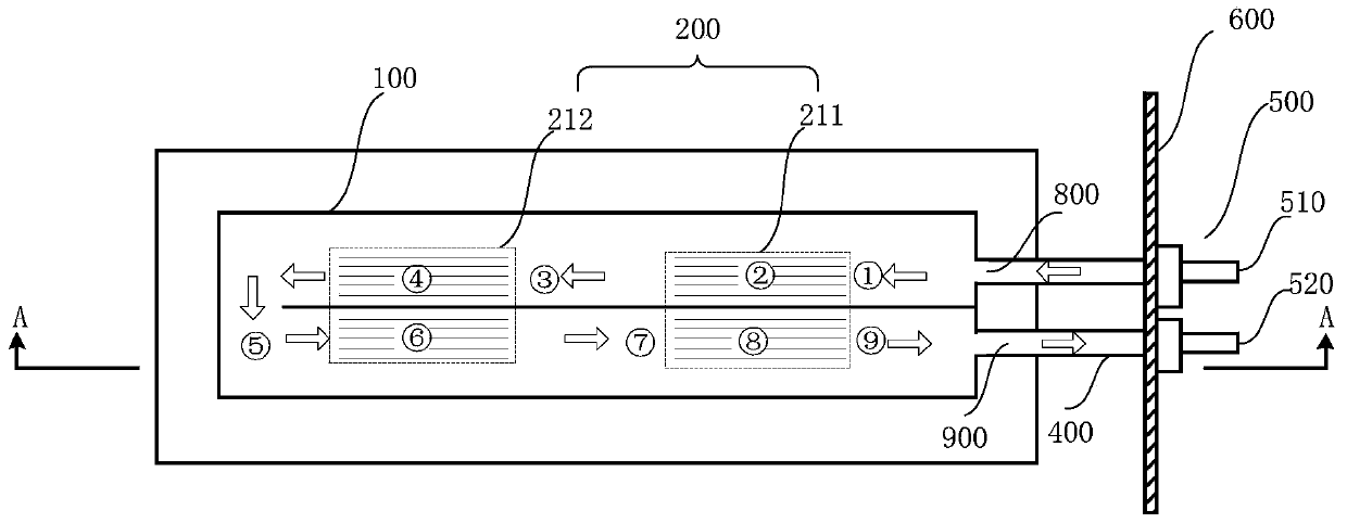
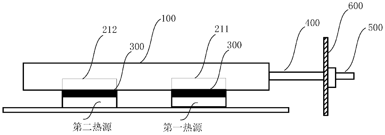
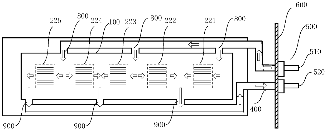
The invention provides a liquid-cooled cold plate device. The liquid-cooled cold plate device comprises a micro-channel cold plate, at least two micro-channel groups, at least one liquid inlet and atleast one liquid outlet, wherein the micro-channel cold plate is used for dissipating heat of an electronic system, the at least two micro-channel groups are arranged inside the micro-channel cold plate; the at least one liquid inlet is formed in the micro-channel cold plate and is used for allowing a cooling liquid to flow in; the at least one liquid outlet is arranged on the micro-channel cold plate and is used for allowing the cooling liquid to flow out; the cooling liquid entering the liquid inlet is divided into one cooling liquid branch; and the cooling liquid branch flows back and forththrough the micro-channel group. The micro-channel cold plate is combined with the micro-channel groups, so that the heat dissipation efficiency is greatly improved, the front-back heat cascade influence is reduced, and the efficient heat dissipation of the electric system is realized.

Description

technical field [0001] The invention belongs to the technical field of refrigeration, and relates to a cooling device, in particular to a liquid-cooled cold plate device. Background technique [0002] With the development of electronic technology and the improvement of chip technology, the volume of electronic components is getting smaller and smaller, and the heat emitted per unit volume is also increasing. In order to maintain the normal working condition of electronic components, a good heat dissipation device is essential. At present, mainstream servers mainly rely on forced air cooling to dissipate heat for internal high-power consumption and high-temperature components. However, as the power consumption of electronic components continues to increase, the traditional forced air cooling method can no longer meet the heat dissipation specifications of high heat flux density servers. As a novel heat dissipation solution, liquid cooling technology has gradually become popu...

Claims


Application Information

Patent Timeline
Patent Type & Authority Applications(China)
IPC IPC(8): H05K7/20
CPCH05K7/20272
Inventor 曲中江葛泽稷范垚银
Owner CELESTICA TECH CONSULTANCY SHANGHAI
Learn More