Real-time heart rate detection method based on double cameras

A detection method and dual-camera technology, which can be used in the measurement of pulse rate/heart rate, diagnostic recording/measurement, medical science, etc., can solve the problem of increasing the difficulty of extracting micro-signals of facial parameters, ambient light interference and noise, and image data inconsistencies. Stability and other issues, to achieve the effect of increasing data stability, improving accuracy and stability, reducing signal distortion and jitter

Inactive Publication Date: 2019-10-22
EAST CHINA NORMAL UNIVERSITY
4 Cites 0 Cited by

AI-Extracted Technical Summary

Problems solved by technology

[0006] At present, the interference and noise of ambient light commonly exist in the heart rate detection method based on video, ...

Abstract

The invention discloses a real-time heart rate detection method based on double cameras. The method comprises the following steps of opening the main camera and the reference camera, and alternately shooting a main video and a reference video which contain the images of human faces at the same frame rate; establishing two face detectors for acquiring an interested area of the main camera and an interested area of the reference camera respectively; capturing a background area of the main camera and a background area of the reference camera; calculating the characteristic values of each frame ofthe interested areas and background areas according to noise information extracted from the interested area and background area of the reference camera to obtain a one-dimensional characteristic sequence on a time axis; filtering the one-dimensional characteristic sequence through a low-pass filter to obtain heart rate signals; calculating a heart rate value through a peak value counting method;acquiring a data updating signal sequence in real time and repeating the steps above to calculate a real-time heart rate value. The method reduces signal distortion caused by ambient light interference and greatly improves accuracy and stability in non-contact heart rate detection.

Application Domain

SensorsMeasuring/recording heart/pulse rate

Technology Topic

DistortionReal time acquisition +6

Image

  • Real-time heart rate detection method based on double cameras
  • Real-time heart rate detection method based on double cameras
  • Real-time heart rate detection method based on double cameras

Examples

  • Experimental program(1)

Example Embodiment

[0058] Example
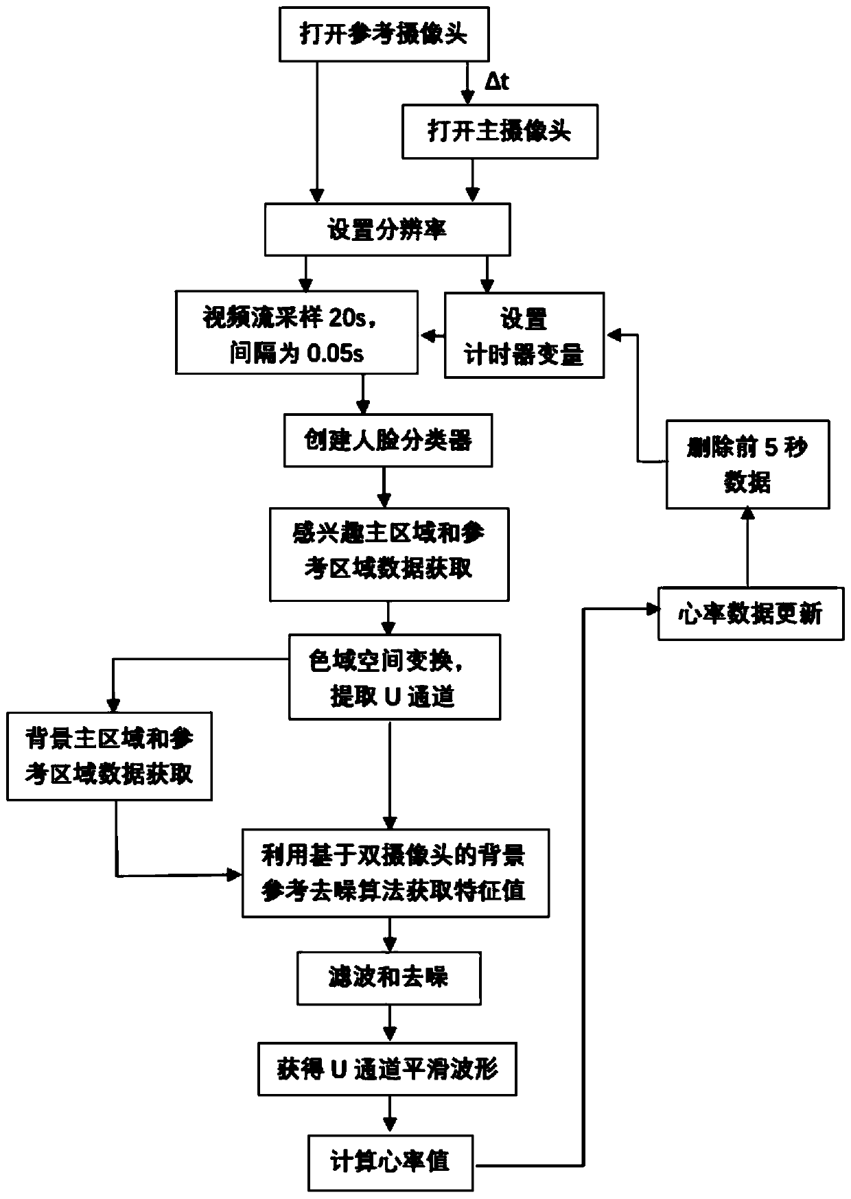
[0059] refer to Figure 1-7 , this embodiment includes the following steps:
[0060] S101: Turn on the main camera and the reference camera, and alternately shoot the main video and the reference video including the human face for 20 seconds at the same frame rate. Take a 30-year-old healthy woman as an example for illustration.
[0061] The steps are specifically:
[0062] Create the main camera object and reference camera object, set the same frame rate fs=20Hz;
[0063] set frame counter frame_counter = 0;
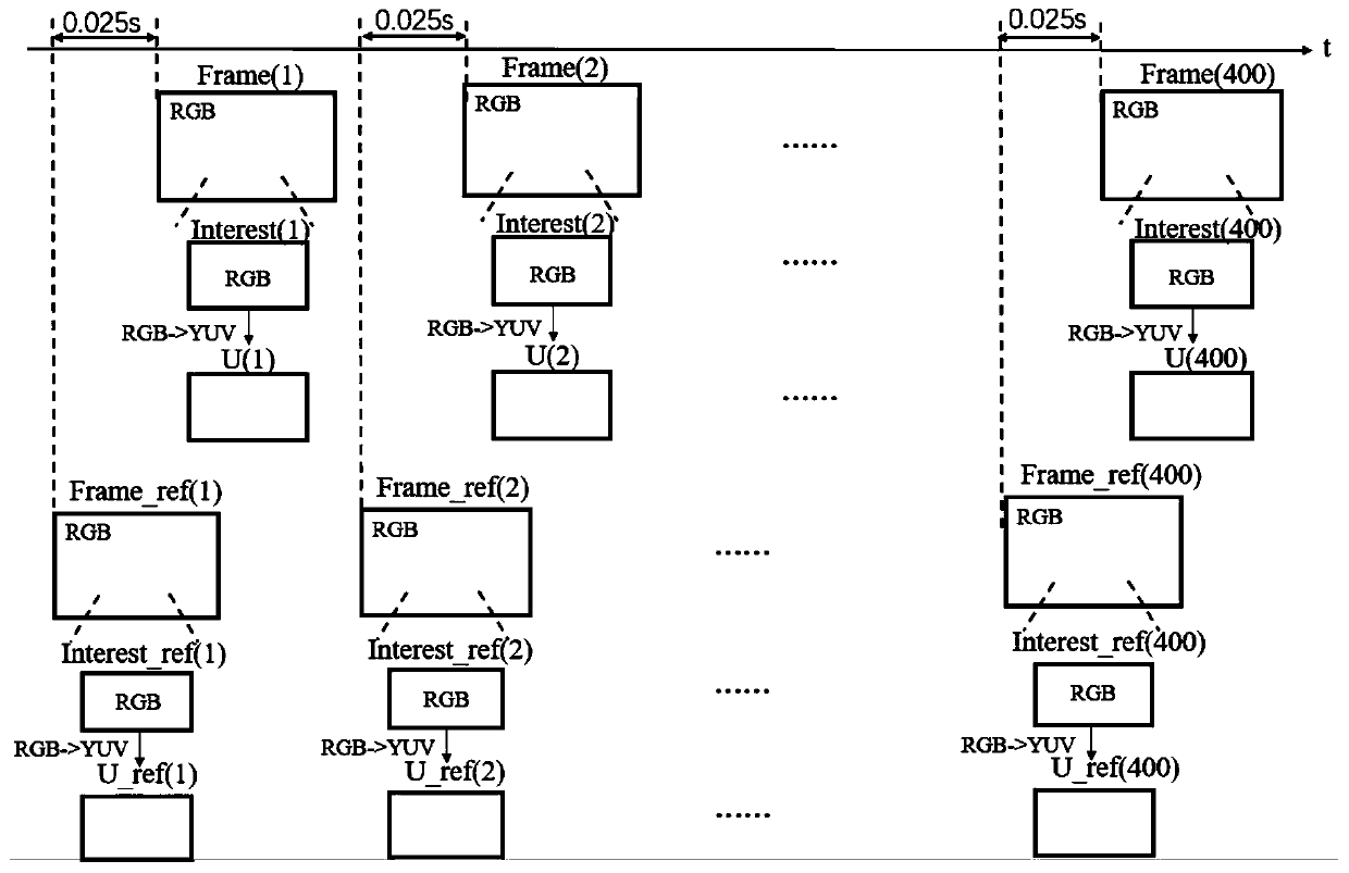
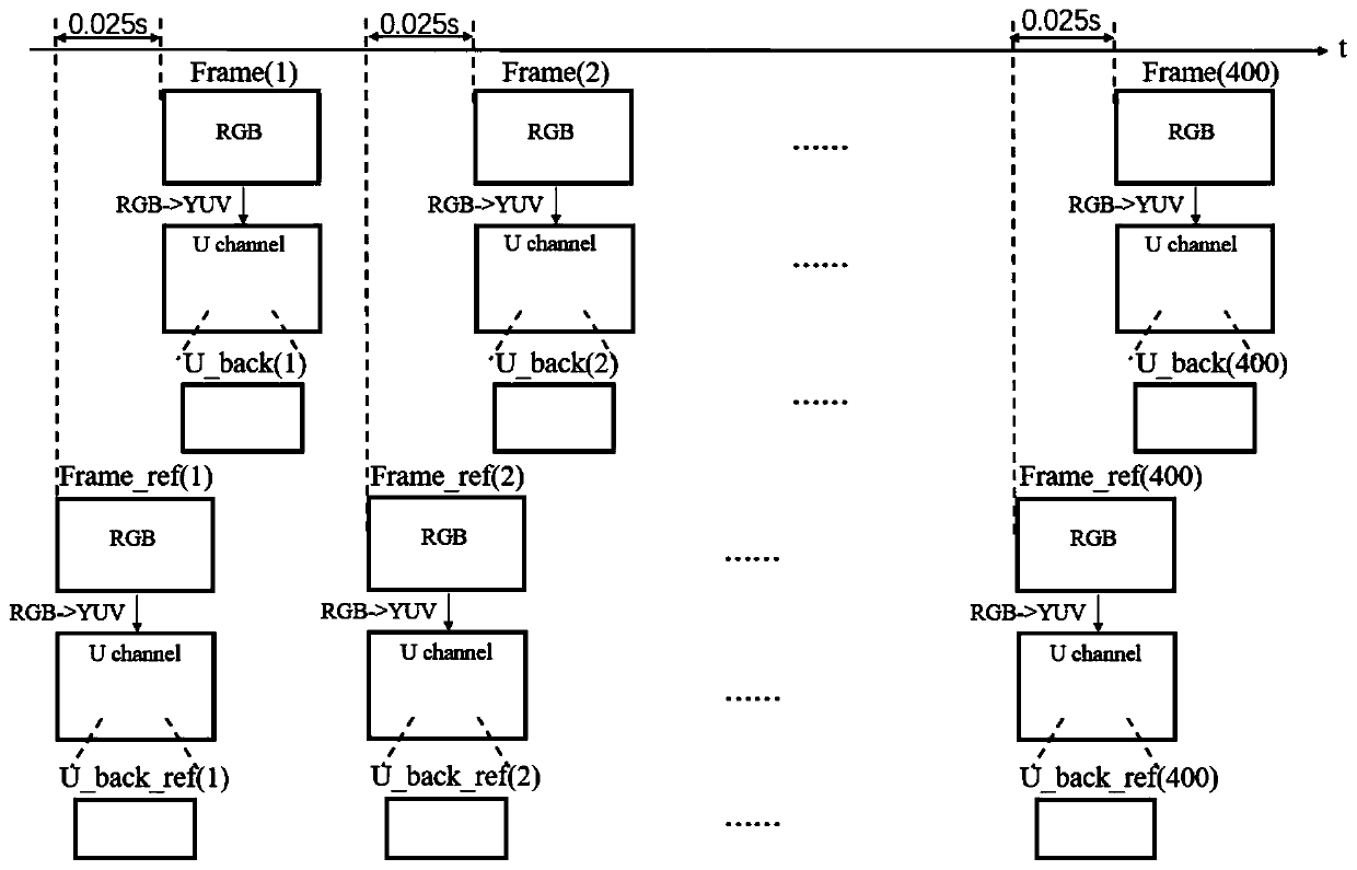
[0064] Turn on the reference camera first, then turn on the main camera after Δt=0.025s, and shoot videos containing human faces at a frame rate of 20Hz for 20s, record the current frame of the reference camera and the current frame of the main camera as Frame_ref(i) and Frame( i), frame_counter=K=400.
[0065] S102: Create two face detectors to obtain the ROI of the main camera and the ROI of the reference camera respectively, extract the U channel data based on the RGB data of each frame, and obtain the U of the ROI of the main camera and the ROI of the reference camera channel sequence, see figure 2.
[0066] The steps are specifically:
[0067] Use the Viola-Jones algorithm to create the face detector, and obtain the starting point coordinates (x, y), (x_ref, y_ref) and face size (w, h) of the main area of ​​the face and the reference area of ​​the face respectively , (w_ref, h_ref); For example, the starting point coordinates of the main face area are (400, 500), the face size is (100, 200), the starting point coordinates of the face reference area are (450, 550), the face size is (100, 200).
[0068] According to the proportion of the face, intercept the area of ​​Frame(i) whose height ranges from 500 to 540 and whose width ranges from 510 to 530, that is, the area of ​​interest of the main camera Interest(i), and intercept Frame_ref(i) whose height range is from 550 to 590 and whose width The area with a range of 560 to 580, that is, the area of ​​interest of the reference camera Interest_ref(i), obtains the RGB channels of the area of ​​interest of the main camera and the area of ​​interest of the reference camera in the current frame;
[0069] The RGB channels of the main camera region of interest and the reference camera region of interest are converted into YUV channels, and two-dimensional U channels U(i), U_ref(i) are extracted respectively; the U channel calculation formula is as follows:
[0070] U=-0.169*R-0.331*G+0.5*B
[0071] The U channel of the region of interest of the main camera in each frame constitutes a sequence U(1), U(2),..., U(400), and the U channel of the region of interest of the reference camera in each frame constitutes a sequence U_ref(1 ), U_ref(2), ..., U_ref(400).
[0072] S103: intercept the background area of ​​the main camera and the background area of ​​the reference camera, and obtain the U channel sequence of the background area of ​​the main camera and the background area of ​​the reference camera, refer to image 3.
[0073] The steps are specifically:
[0074] Create an 8*8 background window;
[0075] Use the background window to move row-by-row and column-by-column in the complement area of ​​the main camera ROI and the reference camera ROI in each frame, and take out the temporary pixel matrix covered by the background window each time, which is respectively recorded as TempArray and TempArray_ref, respectively calculate the variance U_Sigma and U_Sigma_ref of its U channel matrix;
[0076] If U_Sigma>10, continue to move the background window and recalculate; otherwise, use the current TempArray as the background area of ​​the main camera in the current frame, extract the U channel U_back(i) of the background area of ​​the main camera in the current frame, and the main camera in each frame The U channel in the background area constitutes the sequence U_back(1), U_back(2),..., U_back(400);
[0077] If U_Sigma_ref>10, continue to move the background window and recalculate; otherwise, use the current TempArray_ref as the reference camera background area of ​​the current frame, extract the U channel U_back_ref(i) of the reference camera background area in the current frame, and refer to the reference camera in each frame The U channel in the background area constitutes the sequence U_back_ref(1), U_back_ref(2),..., U_back_ref(400);
[0078] S104: Calculate the eigenvalues ​​of the region of interest and the background region of each frame based on the dual cameras, and obtain a one-dimensional feature sequence on the time axis, refer to Figure 4 , in the figure, picture a shows the calculation of the mean and standard deviation of U_ref(i), picture b shows the calculation of the mean and standard deviation of U_back_ref(i), and picture c shows the calculation of the feature value of the i-th frame.
[0079] The steps are specifically:
[0080] Calculate the mean value m_ref(i) and standard deviation σ(i) of the two-dimensional U channel matrix of the reference camera region of interest in the current frame, for example, m_ref(i)=133, σ(i)=6; obtain U_ref(i) For the difference matrix with m_ref(i), the number of pixels whose absolute value exceeds 3*σ(i)=18 in the statistical difference matrix is ​​recorded as Num(i), for example, Num(i)=10;
[0081] Sort the U channel values ​​in the two-dimensional U channel matrix U(i) of the area of ​​interest of the main camera in the current frame from small to large, remove 5 maximum values, remove 5 minimum values, and calculate U(i) Average value m(i), as the eigenvalue of the two-dimensional U channel matrix of the region of interest in the current frame, for example, m(i)=130;
[0082] Calculate the mean m_back_ref(i) and standard deviation σ_ref(i) of the two-dimensional U channel matrix of the reference camera background area in the current frame, for example, m_back_ref(i)=212, σ_ref(i)=2; obtain U_back_ref(i) and The difference matrix of m_back_ref(i), the number of pixels whose absolute value exceeds 3*σ_ref(i) in the statistical difference matrix, is recorded as Num_back(i), for example, Num_back(i)=4;
[0083] Sort the U channel values ​​in the two-dimensional U channel matrix U_back(i) of the main camera background area in the current frame from small to large, remove 2 maximum values, remove 2 minimum values, and calculate the average of U_back(i) Value m_back(i), as the eigenvalue of the two-dimensional U channel matrix of the background area, for example, m_back(i)=210;
[0084] Set the noise removal factor according to the severity of the ambient light change, denoted as β=0.5, calculate U_character(i)=130-0.5*210=25, as the feature value of the i-th frame;
[0085] The feature values ​​of each frame form a one-dimensional feature sequence U_character(1), U_character(2), . . . , U_character(400) on the time axis.
[0086] S105: Use a low-pass filter to filter the one-dimensional feature sequence, and use the filtered one-dimensional feature sequence as the heart rate signal, refer to Figure 5.
[0087] The steps are specifically:
[0088] A 40-order 3Hz Butterworth filter is used to filter the one-dimensional feature sequence U_character(1), U_character(2),..., U_character(400) to obtain a filter sequence Fil(1), Fil(2) with a length of 439 ),...,Fil(439);
[0089] S106: Use the peak counting method to obtain the number of heartbeats, and calculate the heart rate value, refer to Image 6.
[0090] The steps are specifically:
[0091]Scan the filter sequence Fil(1), Fil(2),...,Fil(439) whose length is J, and find the peak value: the Fil(1) does not perform calculation processing; the Fil(2), Fil(3 ),…, Fil(438) are compared with two adjacent points, if the value of this point is larger than the two adjacent points, then this point is considered to be a peak; that is: if Fil(j)>Fil(j-1) And Fil(j)>Fil(j+1), then Fil(j) is a peak point;
[0092] Count the number of peak points within the 20s, recorded as Peak_20s, for example Peak_20s=28;
[0093] Calculate the real-time heart rate value Heart_Rate=Peak_20s*3=84 corresponding to the 20s, that is, the real-time heart rate value of the person in the 20s is 84 beats/min.
[0094] S107: Collect data in real time to update the signal sequence, repeat steps (2)-(6) to calculate the real-time heart rate value, refer to Figure 7.
[0095] Discard the first 5s data Umid(1), Umid(2),...Umid(100) in the 20s, and the latter 15s data form a temporary sequence Umid(1), Umid(2),...Umid(300);
[0096] Update and collect 5s data, supplement after the temporary sequence Umid(1), Umid(2),...Umid(300), so as to realize the update of the sequence Umid(1), Umid(2),...Umid(400), repeat Steps (2) to (6), namely to obtain the real-time heart rate value.

PUM

no PUM

Description & Claims & Application Information

We can also present the details of the Description, Claims and Application information to help users get a comprehensive understanding of the technical details of the patent, such as background art, summary of invention, brief description of drawings, description of embodiments, and other original content. On the other hand, users can also determine the specific scope of protection of the technology through the list of claims; as well as understand the changes in the life cycle of the technology with the presentation of the patent timeline. Login to view more.

Similar technology patents

Separated cavity packaging structure of integrated sensor

InactiveCN105721998AIncreased dorsal spaceimprove signal-to-noise ratio
Owner:GOERTEK INC

Classification and recommendation of technical efficacy words

  • improve signal-to-noise ratio

Touch display device and manufacturing method thereof

ActiveCN102541334Aimprove signal-to-noise ratioavoid craft
Owner:SHANGHAI TIANMA MICRO ELECTRONICS CO LTD

Ethernet connection of airborne radar over fiber optic cable

ActiveUS7158072B1loss variability be also eliminateimprove signal-to-noise ratio
Owner:ROCKWELL COLLINS INC

Chemical sensors based on cubic nanoparticles capped with an organic coating

ActiveUS20100273665A1enhance efficacyimprove signal to noise ratio
Owner:TECHNION RES & DEV FOUND LTD
Why Eureka
Try Eureka