Net rack rod part machining method

A processing method and grid rod technology are applied in metal processing equipment, manufacturing tools, used abrasive processing devices, etc., which can solve the problems of low utilization rate of steel balls, high scrapping rate of steel balls, and slow shot blasting speed, etc., to achieve Improve the utilization rate of steel balls, reduce the fixing time, and avoid the effect of mutual collision

Active Publication Date: 2019-10-22
浙江阳力钢结构股份有限公司
View PDF5 Cites 9 Cited by
  • Summary
  • Abstract
  • Description
  • Claims
  • Application Information

AI Technical Summary

Problems solved by technology

[0002] In the past, steel pipes used in structures such as buildings or bridges were subjected to shot peening in order to remove rust or scale on the surface of steel pipes. Layer and its sundries, so that it can obtain a fine bright surface, improve the tensile and compressive strength of the workpiece, increase the adhesion for the paint protection of the inner surface, achieve the purpose of anti-corrosion, pipe protection, and prolong the service life of the steel pipe. The steel ball thrown out only hits the surface of the steel pipe once, and is bounced off by the steel pipe. The utilization rate of the steel ball is low.

Method used


Image

  • Net rack rod part machining method
  • Net rack rod part machining method
  • Net rack rod part machining method

Examples


Embodiment Construction

[0029] A method for processing grid rods, comprising the following steps:

[0030] a. Steel pipe blanking: the raw steel pipe is cut to the required length by the plasma grid automatic cutting machine, and the blanking groove is formed at one time;

[0031] b. Steel pipe shot blasting derusting: derusting the steel pipe through shot blasting device;

[0032] c. Welding of grid rods: Weld the two cone heads to the two ends of the steel pipe respectively through the automatic welding mechanism;

[0033] d. Paint coating of grid rods: the paint of grid rods is mainly sprayed, and the thickness of the coating is controlled by a dry and wet film thickness gauge;

[0034] e. Marking of rods: the surface of the rods is stamped and marked

[0035] f. Packing and shipping: the rods are bundled by packing;

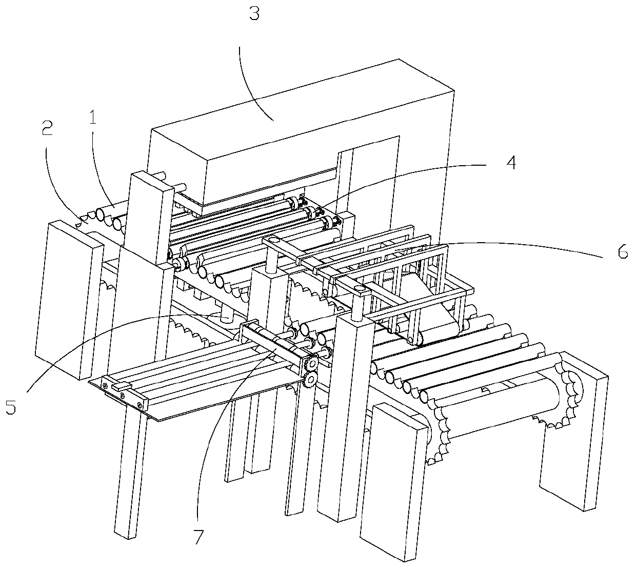
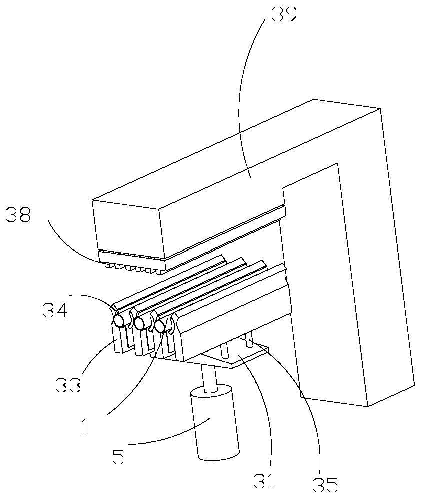
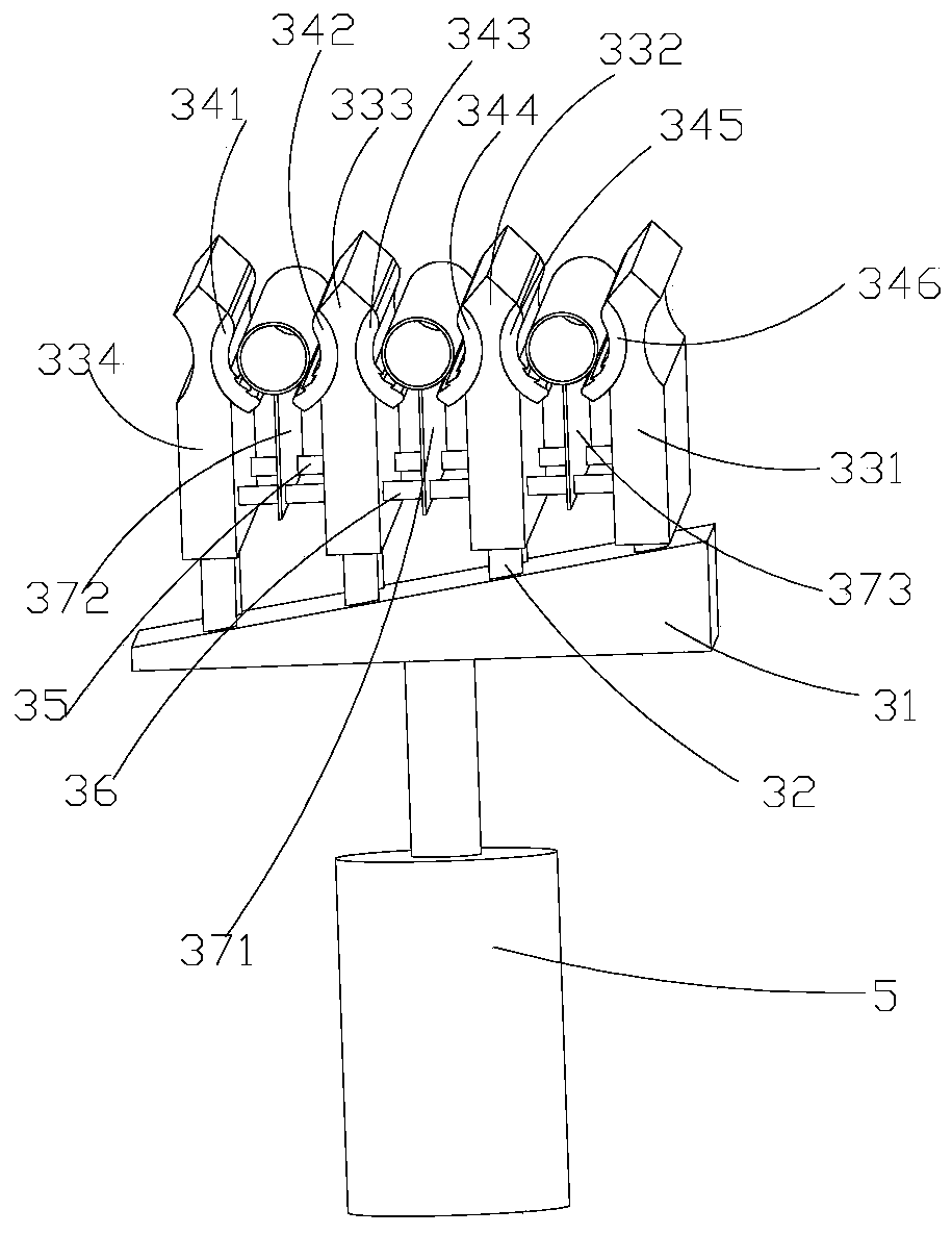
[0036] Such as Figure 1-9The steel pipe shot peening device described in step b includes the steel pipe 1 to be processed, the steel pipe steel pipe delivery assembly 2, the st...


PUM


Abstract

The invention discloses a net rack rod part machining method. The net rack rod part machining method comprises the following steps that shot blasting is conducted on the outer wall of a steel pipe through a steel pipe shot blasting device, a shot blasting dead zone is avoided by clamping the inner wall of the steel pipe, the steel pipe is rotated to enable the outer wall of the steel pipe to be subjected to 360-degree shot blasting treatment, steel balls beat the outer wall of the steel pipe through multiple times of refraction, the beating frequency of the steel balls sprayed out at a time isincreased, collision among the steel balls is reduced, steel pipe surface treatment is accelerated, a sprayer head is inserted into the steel pipe to conduct shot blasting on the inner wall of the steel pipe, and meanwhile the steel balls achieve refraction and collision on the inner wall of the steel pipe. According to the net rack rod part machining method, the structure is simple and easy to operate, the inner wall and the outer wall of the steel pipe can be quickly subjected to shot blasting treatment, the spraying one-time utilization rate of the steel balls is increased, the rejection rate of the steel balls is decreased, and the net rack rod part machining method can be applied to production.

Description

technical field [0001] The present invention relates to a method for processing grid rods, in particular to a steel pipe shot peening. Background technique [0002] In the past, steel pipes used in structures such as buildings or bridges were subjected to shot peening in order to remove rust or scale on the surface of steel pipes. Layer and its sundries, so that it can obtain a fine bright surface, improve the tensile and compressive strength of the workpiece, increase the adhesion for the paint protection of the inner surface, achieve the purpose of anti-corrosion, pipe protection, and prolong the service life of the steel pipe. The steel ball thrown out only hits the surface of the steel pipe once, and is bounced off by the steel pipe. The steel ball utilization rate is low and the shot blasting speed is slow. At the same time, the steel balls collide with each other, and the steel ball scrap rate is high. Contents of the invention [0003] In order to overcome the defi...

Claims


Application Information

Patent Timeline
Patent Type & Authority Applications(China)
IPC IPC(8): B24C1/08B24C5/04B24C9/00B24C3/32B24C3/12
CPCB24C1/086B24C3/12B24C3/32B24C5/04B24C9/00
Inventor 张飞金国军
Owner 浙江阳力钢结构股份有限公司
Why Eureka
Try Eureka