Oil separator

A technology of oil separator and oil plate, which is applied in the direction of chemical instruments and methods, grease/oily substance/floating matter removal device, flotation water/sewage treatment, etc., can solve the problem of destroying the state of liquid stratification, and reduce the Residue, effect-enhancing, efficiency-enhancing effects

Pending Publication Date: 2019-10-22
GUANGZHOU HENGDE ENVIRONMENTAL PROTECTION TECH
View PDF1 Cites 18 Cited by
  • Summary
  • Abstract
  • Description
  • Claims
  • Application Information

AI Technical Summary

Problems solved by technology

[0007] This kind of oil separation device scrapes the oil through the oil scraping device. The oil scraping device includes an endless transmission belt and an oil scraping plate. In the process of forward transport, the layered state of the liquid may be destroyed, so that the oil and water are mixed again, resulting in more water mixed with the oil transferred to the oil collection tank, thus forming a second oil-water mixing in the oil collection tank, resulting in Further oil-water separation operations are required, therefore, it is necessary to develop an oil separator with higher oil-water separation

Method used


Image

  • Oil separator
  • Oil separator
  • Oil separator

Examples


Embodiment 1

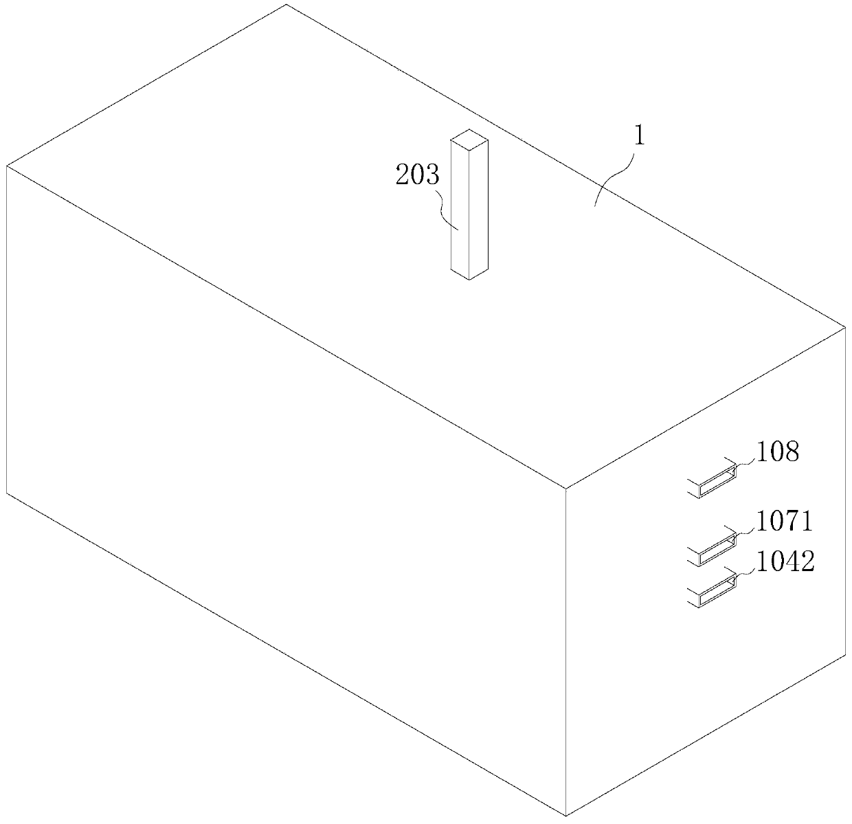
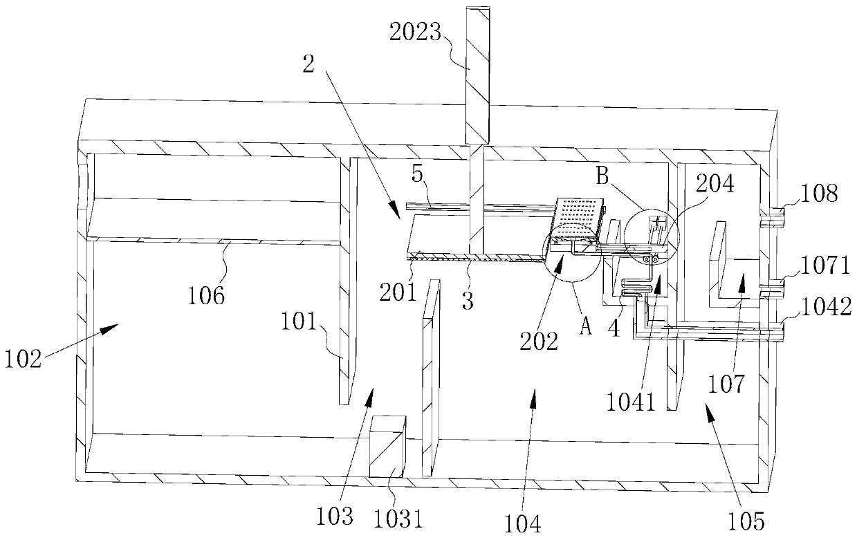
[0054] refer to figure 1 as well as figure 2 , this embodiment discloses an oil separator, comprising a box body 1, a partition 101 is arranged inside the box body 1, and the partition plate 101 divides the space inside the box body 1 into a solid-liquid separation chamber 102, a bubble generation chamber 103, The oil-water separation chamber 104 and the drainage chamber 105, and the solid-liquid separation chamber 102 are provided with a filter screen 106 for filtering solid impurities and realizing solid-liquid separation;

[0055] The bubble generating chamber 103 is provided with a bubble generator 1031, and the oil-water separation chamber 104 is provided with an oil collection tank 1041 and an oil-water separation device 2. In this embodiment, the bubble generator 1031 is a commonly used microbubble generator 1031 on the market. The device 1031 generates air bubbles, and the floating air bubbles carry the oil in the sewage to float up.

[0056] refer to figure 1 with...

Embodiment 2

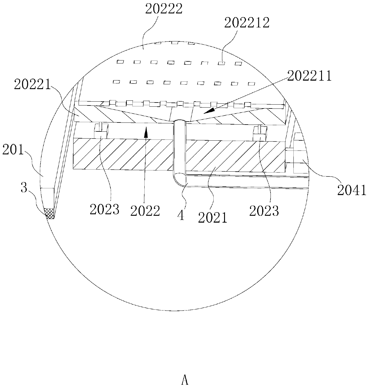
[0076] refer to Figure 5 as well as Image 6 , this embodiment discloses another oil trap, based on Embodiment 1, and the difference from Embodiment 1 is that the oil scraper 202 includes a base 2021 and an oil scraper 2022, and the base 2021 is provided with a receiving groove 20211, The oil scraper 202 is rotatably installed in the accommodation groove 20211, and the bottom of the accommodation groove 20211 is provided with an oil receiving groove 20212, and one side of the oil scraper 202 is provided with an oil scraper protrusion 20223 that abuts against the lower surface of the oil absorber 201, and the accommodation groove 20211 A rotary drive assembly 20213 is provided inside to drive the oil scraper 202 to turn over. The rotary drive assembly 20213 is set in the receiving groove 20211 and located at one end where the oil scraper 2022 of the oil scraper 202 is located. In this embodiment, the rotary drive assembly 20213 includes Rotate and drive the telescopic cylinde...


PUM


Abstract

The invention discloses an oil separator. The oil separator comprises a box body, a solid-liquid separation chamber, a water-oil separation chamber and a water discharge chamber are arranged in the box body, an oil collection trough and an oil-water separation device are arranged in the oil-water separation chamber, the oil-water separation device comprises an oil adsorbing plate, an oil scrapingplate, a vertical driving assembly and a horizontal driving assembly, the lower surface of the oil adsorbing plate is provided with an oil adsorbing sponge layer, the oil-water separation device further comprises an oil guiding tube, one end of the oil guiding tube is connected with the oil scraping plate, the other end of the oil guiding tube extends to the oil collection trough, and the oil guiding tube receives oil scraped off by the oil scraping plate and guides the oil into the oil collecting trough. The vertical driving assembly drives the oil adsorbing plate to contact the liquid surface in the oil-water separation chamber, the oil adsorbing sponge layer adsorbs the oil, the vertical driving assembly drives the oil adsorbing plate to rise, the horizontal driving assembly drives theoil scraping plate to abut against the oil absorbing sponge layer, and the oil adsorbed by the oil adsorbing sponge layer is scraped by the oil scraping plate, goes through the oil guiding tube, and is collected into the oil collecting trough, so the water doped in the separated oil is reduced, and the trouble of secondary oil-water separation is reduced.

Description

technical field [0001] The invention relates to the field of oil-water separation, in particular to an oil trap. Background technique [0002] The so-called oil separator is a special equipment for separating impurities, oil and water in the oily wastewater of catering. As long as the sources of catering wastewater include hotels, hotels, canteens, etc., according to incomplete statistics, the discharge of catering wastewater accounts for about 3% of the urban domestic sewage discharge, but the BOD5 (biochemical oxygen demand for five days) and CODcr ( The content of dichromate oxygen demand) accounts for about 1 / 3 of the total load. It can be seen that catering wastewater is a high-concentration pollution source and one of the main causes of water pollution around cities. [0003] At present, oil-water separation is mainly based on the density or chemical properties of water and oil, using the principle of gravity sedimentation or other physical and chemical methods to rem...

Claims


Application Information

Patent Timeline
Patent Type & Authority Applications(China)
IPC IPC(8): C02F1/40C02F1/24B01D17/022B01D17/028B01D17/032
CPCB01D17/0202B01D17/0211B01D17/0214C02F1/24C02F1/40
Inventor 王鑫琦
Owner GUANGZHOU HENGDE ENVIRONMENTAL PROTECTION TECH
Why Eureka
Try Eureka