
Two-phase flow municipal sludge treatment device

A technology of urban sludge and treatment device, which is applied in sludge treatment, water/sludge/sewage treatment, dehydration/drying/concentrated sludge treatment, etc. Exchange and other issues to achieve the effect of prolonging the time, not easy to accumulate, and increasing the contact area

Inactive Publication Date: 2019-10-22
上海华阜科技发展有限公司
View PDF9 Cites 0 Cited by
  • Summary
  • Abstract
  • Description
  • Claims
  • Application Information

AI Technical Summary

Problems solved by technology

[0004] However, the sludge directly enters the drying chamber 12, which often causes accumulation, and the inside of the accumulated sludge is not easy to exchange heat with the high-temperature flue gas, resulting in low drying efficiency of the sludge, so it needs to be improved

Method used


Image

  • Two-phase flow municipal sludge treatment device
  • Two-phase flow municipal sludge treatment device
  • Two-phase flow municipal sludge treatment device

Examples


Embodiment

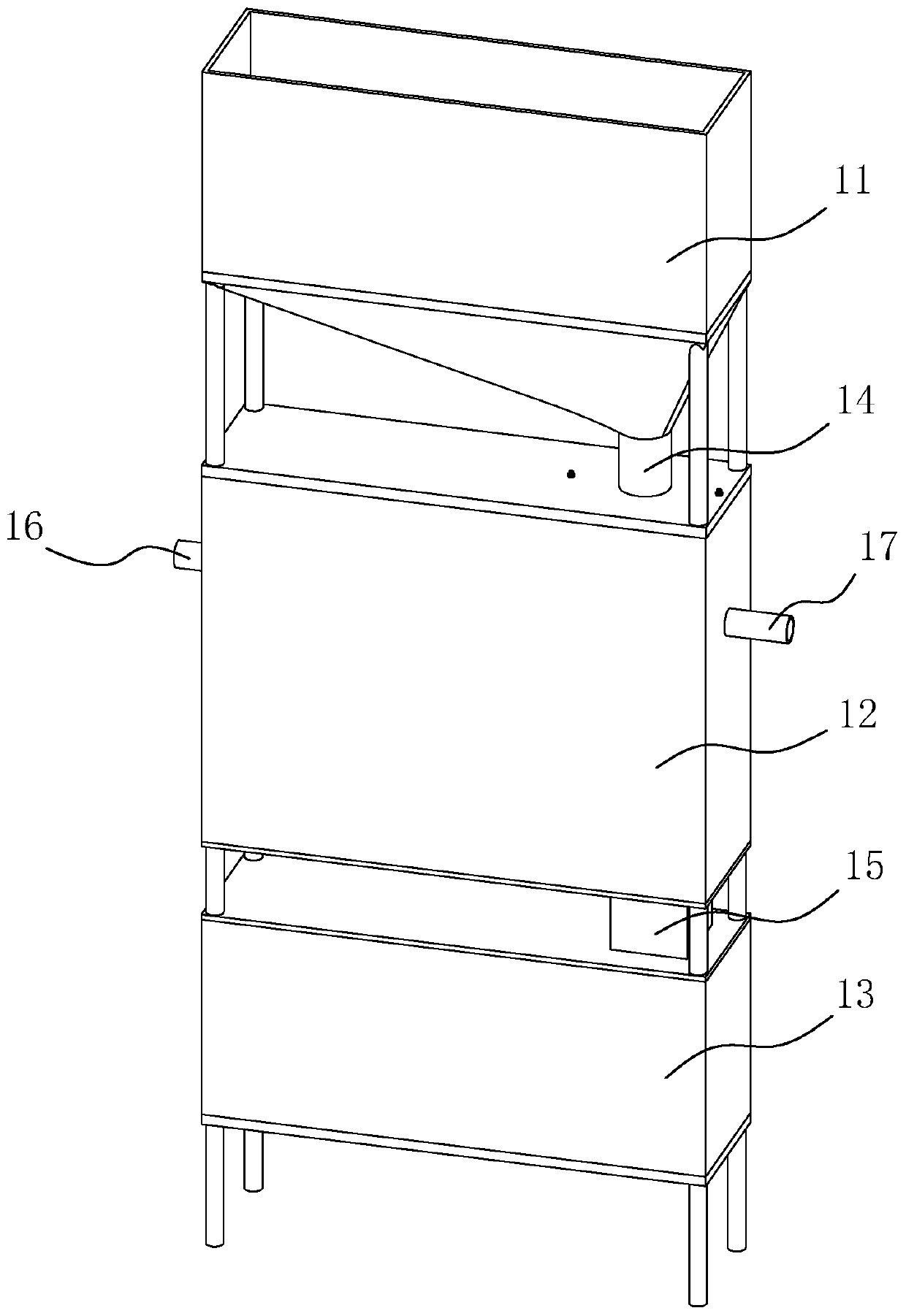
[0044] A two-phase flow municipal sludge treatment device, referring to figure 1 , which includes a wet mud bin 11, a drying bin 12 and a dry mud bin 13 connected in sequence. The wet mud bin 11 communicates with the drying bin 12 through the feed pipe 14 , and the drying bin 12 communicates with the dry mud bin 13 through the discharge pipe 15 . The sidewalls at both ends of the drying chamber 12 are respectively pierced and welded with a flue gas inlet 16 and a flue gas outlet 17 .

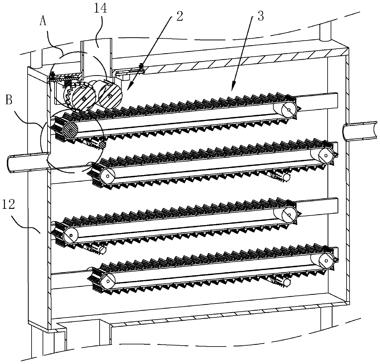
[0045] refer to figure 2 , The drying bin 12 is located below the feed pipe 14 and is provided with an extruding device 2 , and the drying bin 12 is located below the extruding device 2 and is provided with a feeding device 3 .

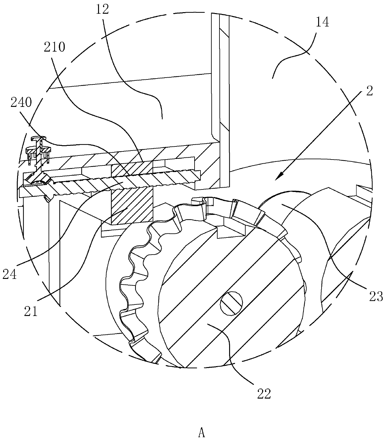
[0046] refer to image 3 The inner top wall of the drying bin 12 is located on both sides of the feed pipe 14 and is symmetrically provided with chute 210 , and the sliding connection in the chute 210 is fitted with a slider 21 , and the cross section of the slider...


PUM


Abstract

The invention discloses a two-phase flow municipal sludge treatment device, relates to the technical field of sludge treatment equipment, and aims to solve the technical problem of low drying efficiency. The invention adopts the key points of the technical scheme that an extrusion device and a feeding device are arranged in a drying bin; the extrusion device comprises a pair of extrusion rollers symmetrically arranged on the two sides under a feeding pipe, a gap is reserved between the two extrusion rollers, the extrusion rollers are rotationally connected with the inner wall of the drying bin, and extrusion drive parts for driving the extrusion rollers to rotate are fixedly arranged on the inner wall of the drying bin; the feeding device comprises a plurality of pairs of feeding rollers,the feeding rollers are rotationally connected with the inner wall of the drying bin, a feeding drive part for driving the feeding rollers is fixedly arranged on the inner wall of the drying bin, feeding conveyer belts are arranged on the outer sides of one pair of feeding rollers in a surrounding manner, and the adjacent feeding conveyor belts rotates in opposite directions and are distributed ina staggered manner in the vertical direction; sludge is extruded into a narrower sheet shape and is transported in the drying bin for a long time through the plurality of feeding conveyor belts, therefore, the drying efficiency is higher.

Description

technical field [0001] The invention relates to the technical field of sludge treatment equipment, more specifically, it relates to a two-phase flow urban sludge treatment device. Background technique [0002] The two-phase flow municipal sludge treatment device is a device that separates sludge from water and mud. [0003] A kind of two-phase flow municipal sludge treatment device in the prior art refers to Figure 8 As shown, it includes a wet mud bin 11, a drying bin 12 and a dry mud bin 13 connected in sequence, the wet mud bin 11 communicates with the drying bin 12 through a feed pipe 14, and the drying bin 12 communicates with the drying bin through a discharge pipe 15. The mud bin 13 is connected, and the side walls at both ends of the drying bin 12 are respectively pierced with a flue gas inlet 16 and a flue gas outlet 17 , and the flue gas outlet 17 is connected to a condenser 18 . When in use, the sludge in the wet mud bin 11 enters the drying bin 12 from the feed...

Claims


Application Information

Patent Timeline
IPC IPC(8): C02F11/121C02F11/13
CPCC02F11/121C02F11/13
Inventor 王峰
Owner 上海华阜科技发展有限公司
Features
  • Generate Ideas
  • Intellectual Property
  • Life Sciences
  • Materials
  • Tech Scout
  • Unparalleled Data Quality
  • Higher Quality Content
  • 60% Fewer Hallucinations
Learn More