Optical fiber manufacturing technology

A manufacturing process and optical fiber technology, applied in the direction of manufacturing tools, glass manufacturing equipment, etc., can solve the problems of affecting the wire drawing operation, the eccentricity of the glass cover, and the inability to cover the tapered transition area well, and achieve the effect of reliable work

Active Publication Date: 2019-10-22
FUTONG GROUP CO LTD +1
View PDF7 Cites 1 Cited by
  • Summary
  • Abstract
  • Description
  • Claims
  • Application Information

AI Technical Summary

Problems solved by technology

[0004] Due to the problem of welding of auxiliary rods, the position of some auxiliary rods and the main body will be staggered (the axes are not on the same straight line), which will cause the glass cover to be off-center after installation, and the glass cover cannot cover the tapered transition area well, which will affect the drawing operation.

Method used


Image

  • Optical fiber manufacturing technology
  • Optical fiber manufacturing technology
  • Optical fiber manufacturing technology

Examples


Embodiment Construction

[0042] The present invention will be described in detail below in conjunction with the drawings.

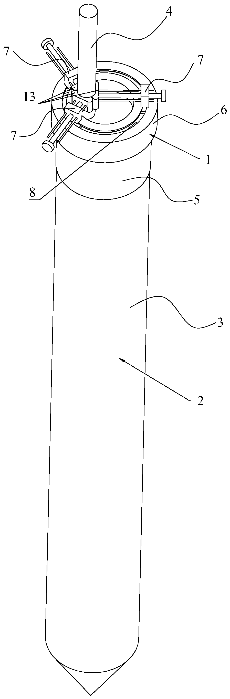
[0043] An optical fiber manufacturing process, including the following steps:

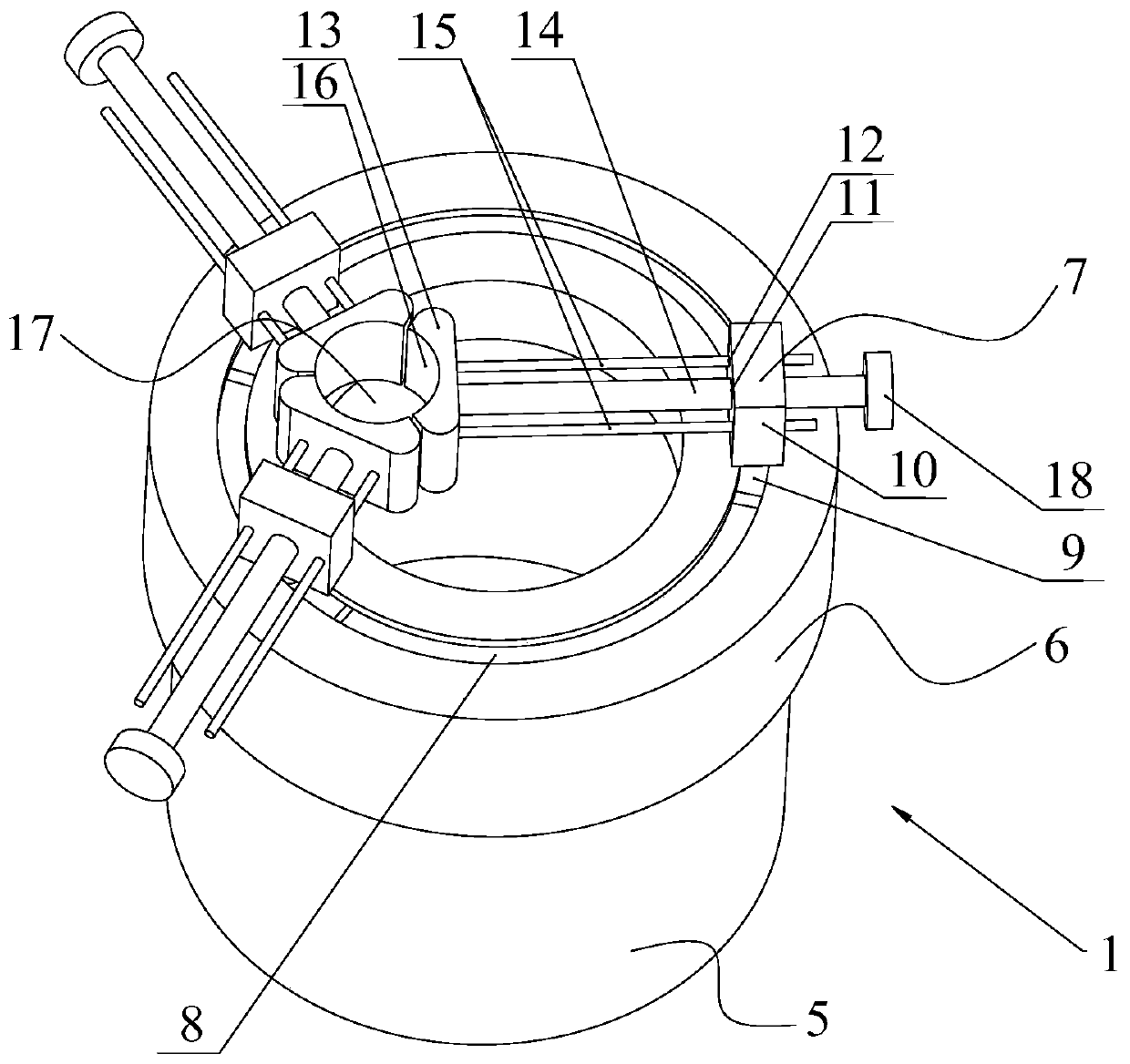
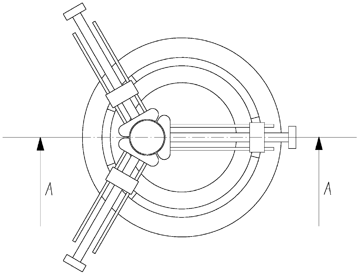
[0044] 1) The glass sleeve with both ends open is sleeved on the upper end of the main body of the preform through the auxiliary rod and the glass sleeve and the main body are arranged coaxially, and the glass sleeve and the auxiliary rod are relatively fixed;

[0045] 2) Clamp the auxiliary rod with a chuck, and control the elevation of the chuck so that the lower part of the preform extends into the drawing furnace;

[0046] 3) The wire drawing furnace is operated to heat the preform, and the lower end of the preform is melted to form a wire.

[0047] The glass sleeve with openings at both ends breaks through the traditional cover structure and can ensure the coaxial line of the glass sleeve and the body of the preform. By fixing the glass sleeve and the auxiliary rod relative to each other, the position of t...


PUM


Abstract

The invention discloses an optical fiber manufacturing technology. The technology comprises the following steps: 1) sleeving the upper end of a preform with a glass sleeve having two open ends throughan auxiliary rod in a manner of coaxially arranging the glass sleeve and the body, and fixing the glass sleeve and the auxiliary rod; 2) clamping the auxiliary rod with a chuck, and controlling the elevation of the chuck to make the lower part of the preform extending into a wire drawing furnace; and 3) allowing the wire drawing furnace to work, and heating the preform to melt the lower end of the preform in order to form a wire. The glass sleeve with two open ends breaks through a traditional cover structure, and can ensure the coaxial line of the glass sleeve and the preform body; and the position of the glass sleeve can be limited by the relative fixation of the glass sleeve and the auxiliary rod, so that the glass sleeve can work reliably.

Description

Technical field [0001] The invention relates to the field of optical fibers, in particular to the manufacturing process of optical fibers. Background technique [0002] The optical fiber is obtained by processing the preform, and the processing of the optical fiber includes a drawing process, a shaping cooling process, a coating process and a curing process. [0003] The preform includes a thick body and an auxiliary rod fixed on the upper end of the body, and the body and the auxiliary rod have a tapered transition. During the drawing operation, in order to ensure the reliable use of the upper part of the preform and prevent a large amount of heat loss, a glass cover is placed on the upper part of the preform. The upper part of the glass cover has a through hole slightly larger than the outer diameter of the auxiliary rod. The outer diameter of the tapered transition part is the same as the outer diameter of the body. [0004] Because of the problem of auxiliary rod welding, the p...

Claims


Application Information

Patent Timeline
Patent Type & Authority Applications(China)
IPC IPC(8): C03B37/025
CPCC03B37/025Y02P40/57
Inventor 曹雨军林中山闫瑞张立永王醒东何园园郝小龙
Owner FUTONG GROUP CO LTD
Why Eureka
Try Eureka