Method for calculating ferroelectric resistance of variable frequency motor under PWM harmonic condition
A variable frequency motor and calculation method technology, which is applied in calculation, measurement of resistance/reactance/impedance, measurement of electrical variables, etc., can solve problems such as slow calculation speed, and achieve the effect of convenient loss
- Summary
- Abstract
- Description
- Claims
- Application Information
AI Technical Summary
Problems solved by technology
Method used
Image
Examples
Embodiment 1
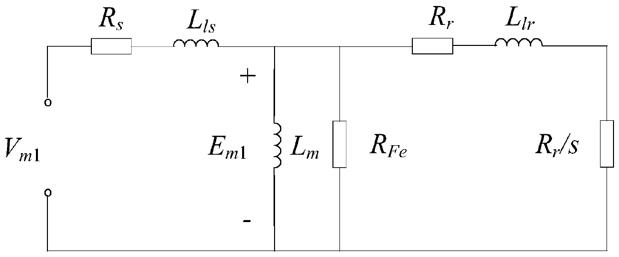
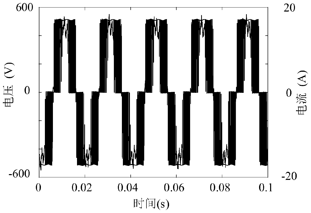
[0118] With a 5.5kW variable frequency induction motor, its parameters are shown in Table 1 respectively. Under rated conditions, the voltage and current waveforms of the two motors are as attached figure 2 shown. Utilize the solution method of the iron consumption resistance that the present invention proposes, calculated its iron consumption resistance with the change situation of the modulation coefficient of rotating speed and PWM frequency converter as attached Figure 4 . Among them, the switching frequency of the inverter is 5kHz. When the speed is lower than the rated synchronous speed, the ratio of the induced potential to the frequency is guaranteed to remain unchanged; when the synchronous speed exceeds the rated synchronous speed, the induced potential is taken as a constant value. It can be seen that the higher the modulation coefficient of the PWM inverter, the higher the speed of the induction motor, and the greater the equivalent resistance of the iron loss....
Embodiment 2
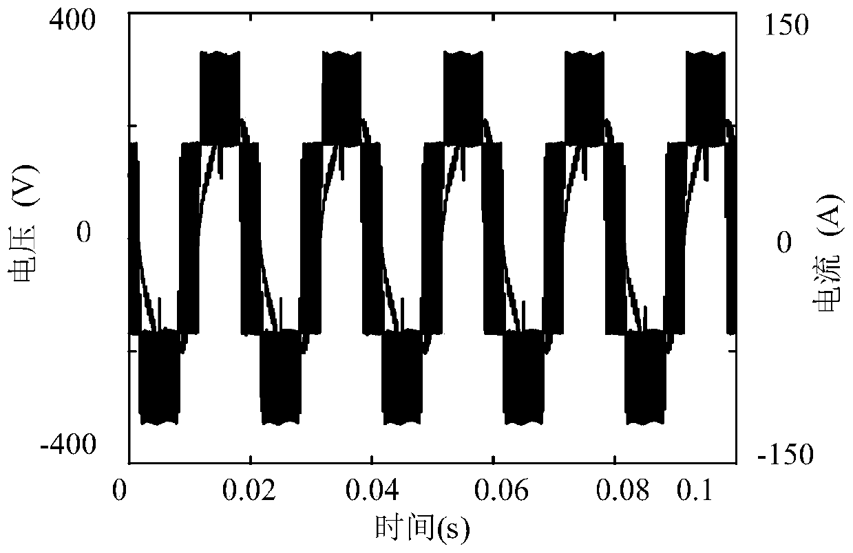
[0120] With a 30kW variable frequency induction motor, its parameters are shown in Table 2 respectively. Under rated conditions, the voltage and current waveforms of the two motors are as attached image 3 shown. Utilize the solution method of the iron consumption resistance that the present invention proposes, calculated its iron consumption resistance with the change situation of the modulation coefficient of rotating speed and PWM frequency converter as attached Figure 5 . Among them, the switching frequency of the inverter is 5kHz. When the speed is lower than the rated synchronous speed, the ratio of the induced potential to the frequency is guaranteed to remain unchanged; when the synchronous speed exceeds the rated synchronous speed, the induced potential is taken as a constant value. It can be seen that the higher the modulation coefficient of the PWM inverter, the higher the speed of the induction motor, and the greater the equivalent resistance of the iron loss. ...
Embodiment 3
[0122] Using the method of the present invention based on the analytical method and the classic model based on the time-step finite element and the subsection variable coefficient model to calculate the frequency conversion induction motor of a specification such as 5.5kW shown in Table 1 under different supply voltage sinusoidal power supply conditions Iron consumption. The comparison between actual measurement and simulation Figure 6a and Figure 6b shown. It can be seen that the values calculated by the method of the present invention and the segmented variable coefficient model are very close to the measured values.
PUM
 Abstract
Description
Claims
Application Information
 - R&D
- Intellectual Property
- Life Sciences
- Materials
- Tech Scout
- Unparalleled Data Quality
- Higher Quality Content
- 60% Fewer Hallucinations
Browse by: Latest US Patents, China's latest patents, Technical Efficacy Thesaurus, Application Domain, Technology Topic, Popular Technical Reports.
© 2025 PatSnap. All rights reserved.Legal|Privacy policy|Modern Slavery Act Transparency Statement|Sitemap|About US| Contact US: help@patsnap.com


