Target detection method based on laser radar and image pre-fusion

A technology of laser radar and target detection, which is applied in image analysis, image enhancement, image data processing, etc., to achieve the effect of improving accuracy

Active Publication Date: 2019-10-22
SOUTHEAST UNIV
View PDF3 Cites 47 Cited by
  • Summary
  • Abstract
  • Description
  • Claims
  • Application Information

AI Technical Summary

Problems solved by technology

At present, there are two fusion schemes: pre-fusion and post-fusion; pre-fusion refers to the target data generated by each sensor independently, and when all sensors complete the generation of target data, the main processor performs data fusion; post-fusion has only one perception The algorith...

Method used


Image

  • Target detection method based on laser radar and image pre-fusion
  • Target detection method based on laser radar and image pre-fusion
  • Target detection method based on laser radar and image pre-fusion

Examples


Embodiment 1

[0045]In the first step, Zhang Zhengyou calibration method is used to obtain the internal parameters of the camera, and the method of manually extracting feature points to solve the rotation offset matrix is ​​used to obtain the external parameters of the lidar and camera;

Embodiment 2

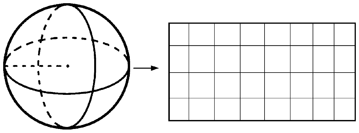
[0047] In the fourth step, the spherical projection of the tagged lidar point cloud dataset includes the following steps: first, the spherical projection of the lidar point cloud dataset is performed, φ represents the angle between the point and the front of the car, and θ represents the point and The calculation formulas of horizontal angle, φ and θ are:

[0048]

[0049]

[0050] Then differentiate the obtained angle to obtain a two-dimensional Cartesian coordinate system, δθ and δφ refer to the resolution of the angle differential

[0051]

[0052]

[0053] Extract the five features of each point in the lidar point cloud dataset: (x, y, z, intensity, range), put them into (i, j), where (x, y, z) is the point coordinates, and the intensity is Radar reflection intensity, range is the distance to the origin

[0054]

[0055] The point cloud is sampled according to the radar harness in the height direction, and 512 equally divided samples are taken in the horizo...

Embodiment 3

[0059] As a further preference of the present invention, the training step of the neural network in the aforementioned fourth step specifically includes the following steps:

[0060] Step 41: Extract two sub-datasets from the lidar point cloud dataset and the image dataset, and the targets in the two sub-datasets are clearly identifiable;

[0061] Step 42, use the above two sub-data sets to train the image and point cloud neural network respectively, so that the convolution layer can fully learn the point cloud obstacle features and image obstacle features, and form the convolution layer parameters of the single-mode detection network;

[0062] Step 43, use the convolution layer parameters of the single-mode detection network trained in step 42 as the features of lidar point cloud data and image data, no longer train, and add a 1×1 convolution block behind, Then use all the data sets for training. During the training process, keep the parameters of the previously trained singl...


PUM


Abstract

The invention relates to a target detection method based on laser radar and image pre-fusion. The laser radar and the camera are combined for calibration; laser radar point cloud data of the visual angle of the camera is obtained; then, before the data is input into the neural network; firstly, spherical projection is performed on a laser radar data set, dense and two-dimensional data is obtained,then an image obtained by laser radar projection and a camera image are taken as two inputs of a network to respectively learn color and three-dimensional features, and finally the features of the two modes are fused through a 1 * 1 convolution block to realize target detection based on radar and pre-vision fusion. The method is different from traditional vision and radar respective detection, finally adopts a weighted post-fusion mode, adopts two corresponding inputs of a laser radar and an image, respectively learns features, and finally performs fusion, so that the accuracy of target recognition can be improved, and the category and three-dimensional information of a target can be obtained at the same time.

Description

technical field [0001] The invention relates to a target detection method based on laser radar and image pre-fusion, and belongs to the technical fields of sensor fusion, artificial intelligence and automatic driving. Background technique [0002] The environmental perception technology of unmanned vehicles mainly uses external sensors, such as laser radar, camera, millimeter wave radar, etc. to detect the surrounding environment, so as to ensure that unmanned vehicles can timely and accurately perceive the safety hazards existing in the road environment. Quickly take measures to avoid traffic accidents; environmental perception is equivalent to the eyes of unmanned vehicles, and plays an irreplaceable role in ensuring the safe driving of unmanned vehicles. [0003] At present, there are two mainstream methods for unmanned vehicle environment perception: vision and lidar. Vision is to obtain the image information of the surrounding environment of the vehicle based on machin...

Claims


Application Information

Patent Timeline
IPC IPC(8): G06T7/80G06T5/00G06T7/30G06N3/04G01S17/02G01S17/93
CPCG06T7/80G06T5/006G06T7/30G06T2207/10044G06T2207/20221G06T2207/30252G01S17/86G01S17/931G06N3/045Y02T10/40
Inventor 殷国栋薛培林吴愿刘帅鹏庄伟超陈浩黄文涵
Owner SOUTHEAST UNIV
Why Eureka
Try Eureka