
Transformer iron chip lamination mechanism, transformer iron chip lamination device and lamination machine

A lamination device and iron core technology, which is applied in the manufacture of inductors/transformers/magnets, electrical components, circuits, etc., can solve the problems of poor lamination accuracy, reduced reliability of lamination machines, and complex structure of lamination machines. Achieve the effect of high lamination efficiency and strong equipment reliability

Active Publication Date: 2019-10-22
四川德华电气有限责任公司
View PDF10 Cites 10 Cited by
  • Summary
  • Abstract
  • Description
  • Claims
  • Application Information

AI Technical Summary

Problems solved by technology

[0004] The lamination accuracy of ordinary lamination machines is poor. In order to make the iron chips fall into the mold accurately, manual auxiliary operations are required, but the efficiency is low; some lamination machines are equipped with devices for precise positioning of iron chips , including a plurality of corresponding electrical components, which not only complicates the structure of the stacking machine, requires regular maintenance, and is expensive, but also requires a certain amount of time for the positioning device to position the iron chips, and the stacking efficiency is still not high, and a large number of Electrical components that reduce the overall reliability of the stacker

Method used


Image

  • Transformer iron chip lamination mechanism, transformer iron chip lamination device and lamination machine
  • Transformer iron chip lamination mechanism, transformer iron chip lamination device and lamination machine
  • Transformer iron chip lamination mechanism, transformer iron chip lamination device and lamination machine

Examples


Embodiment Construction

[0027] In the following, only some exemplary embodiments are briefly described. As those skilled in the art would realize, the described embodiments may be modified in various different ways, all without departing from the spirit or scope of the present invention. Accordingly, the drawings and descriptions are to be regarded as illustrative in nature and not restrictive.

[0028] In describing the present invention, it should be understood that the terms "center", "longitudinal", "transverse", "length", "width", "thickness", "upper", "lower", "front", " Back", "Left", "Right", "Vertical", "Horizontal", "Top", "Bottom", "Inner", "Outer", "Clockwise", "Counterclockwise", "Axial" , "radial", "circumferential" and other indicated orientations or positional relationships are based on the orientations or positional relationships shown in the drawings, which are only for the convenience of describing the present invention and simplifying the description, rather than indicating or im...


PUM


Abstract

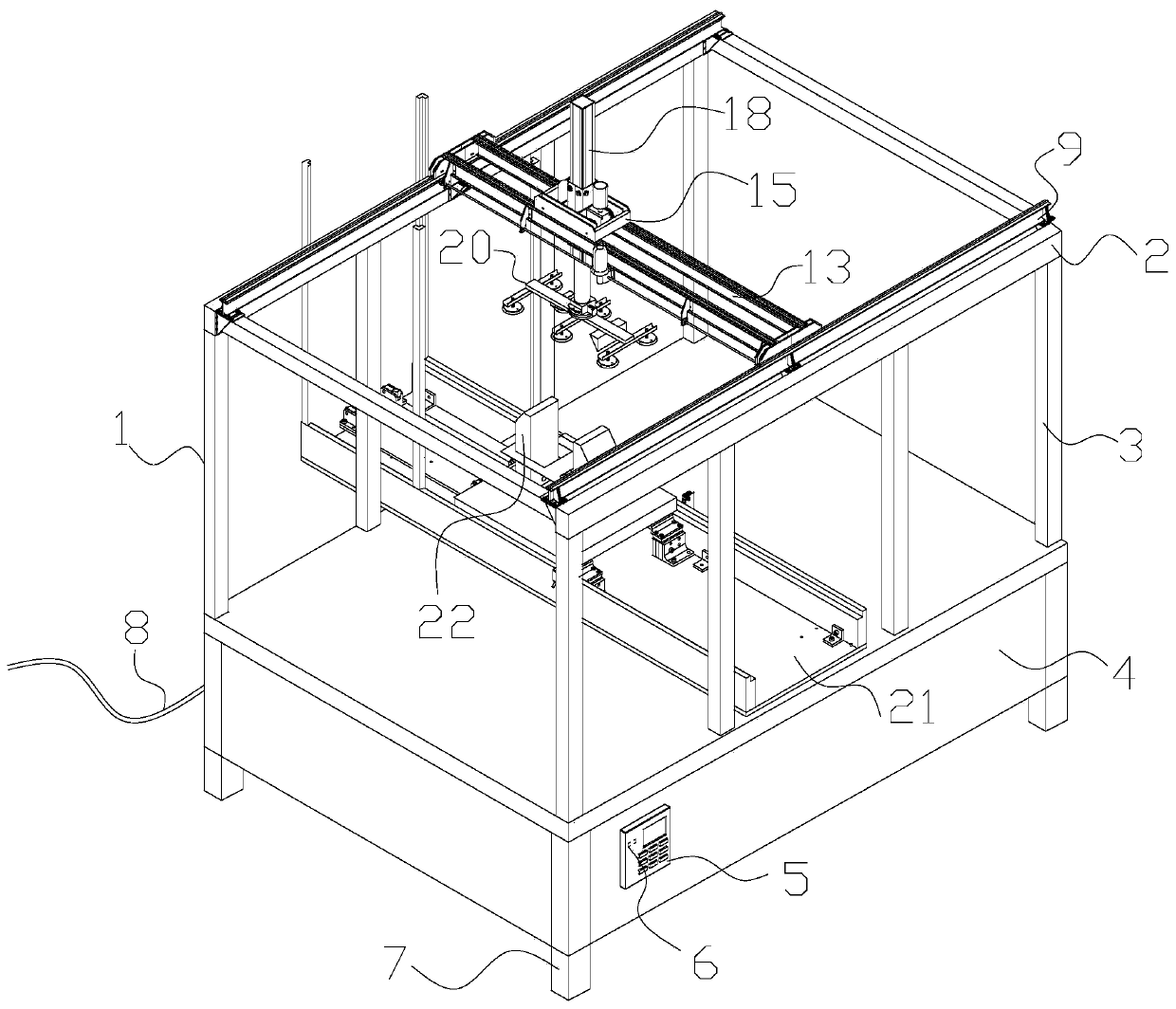
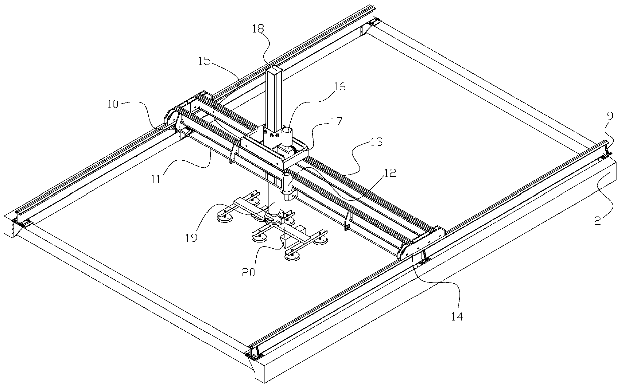
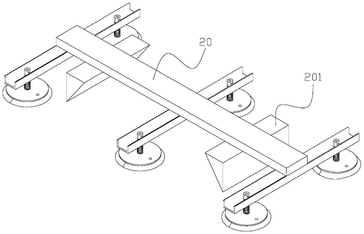
The invention provides a transformer iron chip lamination mechanism, a transformer iron chip lamination device and a lamination machine, and relates to the technical field of automation equipment fortransformer production. The lamination accuracy of a common lamination machine is poor, and the efficiency is low; some lamination machines are additionally provided with devices for accurately positioning iron core sheets, and comprise a plurality of corresponding electric elements, so that the lamination machine has a complex structure, needs regular maintenance and is high in cost, the positioning devices need some time for positioning the iron chip sheets, the lamination efficiency is still not high, and a lot of electrical elements are used to reduce the whole reliability of the lamination machine. When sucking disc frame sucks the iron core sheets to be stacked downwards, a guide piece is matched with a clamping block group to enable the clamping block group to contract, the iron core sheets are easily placed among the clamping blocks, after the sucking disc frame is lifted, the clamping block group stretches under the action of the elastic piece to clamp the iron core sheets, the iron core sheets are fixed at the set positions, the lamination efficiency is high, the iron core sheets are not required to be accurately positioned, a mechanical structure is adopted, and the reliability of the device is high.

Description

technical field [0001] The invention discloses a lamination mechanism, a device and a lamination machine for transformer iron chips, relating to the technical field of automation equipment for transformer production. Background technique [0002] The transformer iron core is the support skeleton used to wind the transformer coil winding, and the existing iron core is actually a structure with a fixed shape formed by laminating multiple silicon steel sheets, and the transformer iron core is often not a single winding post, For example, it usually requires a winding skeleton formed into a "day"-shaped configuration. [0003] In the manufacturing process of the transformer core, it is necessary to use a lamination machine to stack multiple iron chips together according to the corresponding requirements. Ordinary lamination machines use suction cups to absorb the iron chips in sequence, and stack the iron chips in sequence. [0004] The lamination accuracy of ordinary laminatio...

Claims


Application Information

Patent Timeline
Patent Type & Authority Applications(China)
IPC IPC(8): H01F41/02
CPCH01F41/0233
Inventor 张吉安陈楚畅
Owner 四川德华电气有限责任公司
Learn More