Method for laying cable troughs in roadbed

A technology of cable trough and subgrade, which is applied in the direction of cable installation, cable installation device, and cable installation in ground conduits, etc. It can solve problems such as unstable cable trough laying structure, water accumulation in cable trough, and poor construction quality

Active Publication Date: 2019-10-22
RAILWAY ENG RES INST CHINA ACADEMY OF RAILWAY SCI +3
View PDF13 Cites 2 Cited by
  • Summary
  • Abstract
  • Description
  • Claims
  • Application Information

AI Technical Summary

Problems solved by technology

[0004] However, the existing cable tray still has some problems during service
For example, rainwater infiltrates into the subgrade bed through the gap between the cable trench and the surface of the inner subgrade bed, causing water accumulation in the cable trench, soaking the subgrade bed, and even causing problems such as instability of the subgrade slope
At the same time, the existence of the cable trough will affect the drainage of the subgrade bed and form a water blocking effect, which leads to an increase in the water content in the subgrade bed, causing problems such as subgrade frost heave
In addition, since the subgrade cable trough is usually set on the surface of the subgrade bed, and there are many crossing pro

Method used


Image

  • Method for laying cable troughs in roadbed
  • Method for laying cable troughs in roadbed
  • Method for laying cable troughs in roadbed

Examples


Embodiment 1

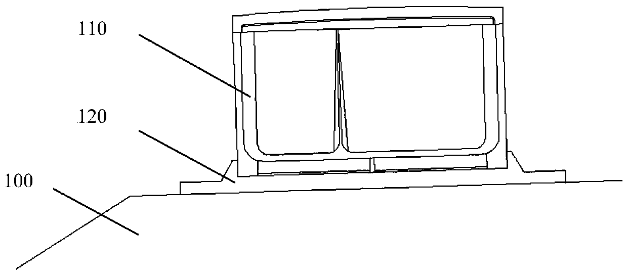
[0034] In this embodiment, the cable duct 110 is arranged on the road shoulder 100 along the extending direction of the line.

[0035] According to the present invention, adjacent sub-cable ducts are connected through pipe joints, and fixedly connected with the road shoulder 100 through the fixed backing plate 120 at the pipe joint connection. The fixed backing plate 120 is fixedly installed on the road shoulder 100 through anchor bolts. The fixed backing plate 120 is provided with a first card slot, and the cable duct pipe joint is locked into the first card slot for fixed installation.

[0036] In the construction process of laying the cable trench, the fixed backing plate 120 is first installed at the set position, and the fixed backing plate 120 is fixed to the road shoulder 100 of the foundation bed through an anchoring method. card slot. In order to improve the laying stability of the cable duct 110 , a waterproof structural adhesive is provided between the first slot ...

Embodiment 2

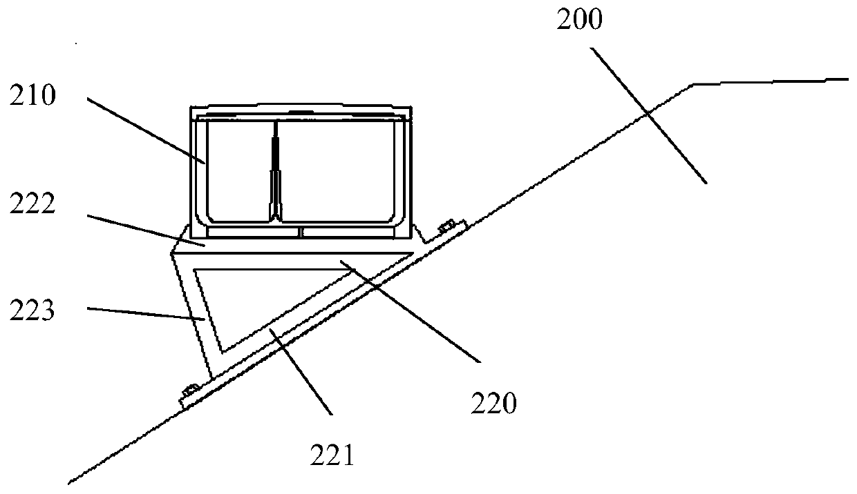
[0038] In this embodiment, a cable groove 210 is arranged on the outer side of the road shoulder 200 along the extending direction of the line.

[0039] According to the present invention, the cable duct 210 is arranged on the slope surface of the road shoulder 200 through the supporting frame 220 . Such as figure 2 As shown, the support frame 220 is fixed on the slope of the road shoulder 200 . The supporting frame 220 includes a fixing plate 221 and a supporting plate 222 connected at an acute angle, and a connecting plate 223 for connecting the fixing plate 221 and the supporting plate 222 is provided between the fixing plate 221 and the supporting plate 222 . Thus, the support frame 220 forms a stable triangular support structure, which can effectively ensure the stability of the support frame 220 for the cable duct. The acute angle between the fixed plate 221 and the support plate 222 is set according to the inclination angle of the slope surface of the road shoulder, ...

Embodiment 3

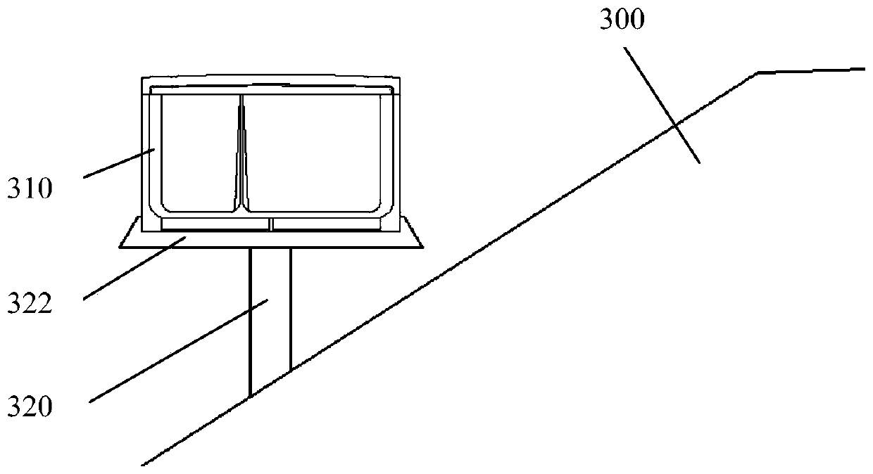
[0044] In this embodiment, a cable groove 310 is arranged on the outer side of the road shoulder 300 along the extending direction of the line.

[0045] According to the present invention, the cable duct 310 is laid on the slope surface of the road shoulder 300 through the pier 320 . Such as image 3 As shown, the buttresses 320 are fixedly arranged on the slope surface of the road shoulder 300 and evenly spaced along the longitudinal direction. In one embodiment, the buttress 320 adopts a prefabricated steel casing, preferably a seamless steel pipe. According to the invention, the steel casing is prefabricated together with the shoulder concrete. Before pouring the road shoulder construction, the steel sleeves are placed longitudinally at a distance of two meters, and then poured in the slope of the road shoulder to form the buttress 320 . The cable duct 310 is laid on the outside of the road shoulder 300 through the pier 320 and above the slope surface of the road shoulde...


PUM


Abstract

The invention provides a method for laying cable troughs in a roadbed. The method comprises the following steps of: providing cable troughs; and arranging the cable troughs in road shoulders of the roadbed or outside the road shoulders or at slope toes of a foundation bed of the roadbed. According to the invention, the cable troughs can be separated from the foundation bed for arrangement, so thatthe problems of water accumulation in the cable troughs, foundation bed soaking, unsmooth drainage of the roadbed and the like can be effectively avoided. In addition, the cable troughs can be laid by adapting to road sections with special working conditions, the integrity of the cable troughs and the stability of the roadbed are effectively guaranteed, the service environment of cables is improved, and the service life of the cables and railway operation safety are guaranteed.

Description

technical field [0001] The invention relates to the technical field of railway roadbed cable troughs, in particular to a method for laying cable troughs on the roadbed. Background technique [0002] In recent years, my country's railway technology has developed rapidly, especially the high-speed railway. During the operation of the high-speed railway, in order to facilitate the maintenance and repair of the high-speed railway and ensure the safety of operation, various cables are usually laid in the form of cable troughs. As an important infrastructure, the cable tray is responsible for maintaining the normal power supply and communication of the line, and is the artery of the high-speed railway. [0003] At present, the cable ducts of high-speed railway subgrades in my country usually adopt the form of common communication signal ducts and separate electric power ducts, and the cable ducts and cover plates are prefabricated with reinforced concrete materials. The existing...

Claims


Application Information

Patent Timeline
IPC IPC(8): H02G1/00H02G9/04
CPCH02G1/00H02G9/04
Inventor 叶阳升杜晓燕常凯马伟斌蔡德钩杨常所王志伟郭小雄赵鹏马超锋蒋函珂高宁
Owner RAILWAY ENG RES INST CHINA ACADEMY OF RAILWAY SCI
Why Eureka
Try Eureka