
Uncertain parameter interference suppression method for LCL filter grid-connected inverter

A filter parameter and interference suppression technology, applied in the direction of output power conversion devices, electrical components, etc., can solve the problems of grid impedance waveform, damage reduction, etc., and achieve the effect of a robust current control method

Inactive Publication Date: 2019-10-22
HARBIN INST OF TECH +1
View PDF0 Cites 3 Cited by
  • Summary
  • Abstract
  • Description
  • Claims
  • Application Information

AI Technical Summary

Problems solved by technology

However, the premise of rationally configuring parameters to achieve the purpose of order reduction is that each parameter of the system can stably meet the ideal ratio. Changes in the environment will inevitably cause waveforms, so that the effect of reducing the order will be destroyed.

Method used


Image

  • Uncertain parameter interference suppression method for LCL filter grid-connected inverter
  • Uncertain parameter interference suppression method for LCL filter grid-connected inverter
  • Uncertain parameter interference suppression method for LCL filter grid-connected inverter

Examples


specific Embodiment 1

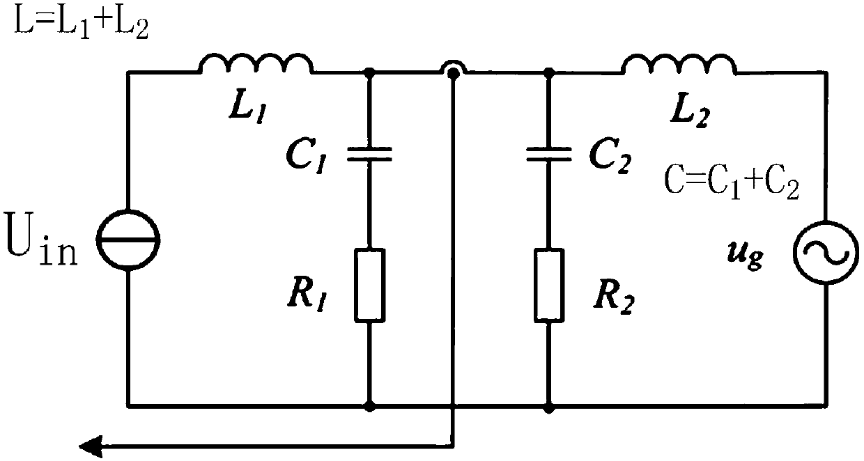
[0072] according to figure 1 As shown in the flow chart, the present invention provides an uncertain parameter interference suppression method for an LCL filter grid-connected inverter, comprising the following steps:

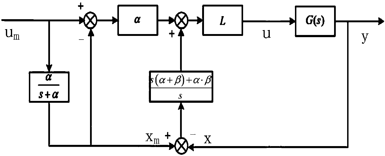
[0073] Step 1: Set the LCL filter parameters, simplify the third-order LCL filter into a first-order system, and establish the transfer function of the control system based on time-delay control;

[0074] Step 2: According to the mathematical model of the control system based on time-delay control, determine the set point tracking response, establish the state equation corresponding to the expected reference model, and obtain the preliminary input expression according to the state equation corresponding to the expected reference model;

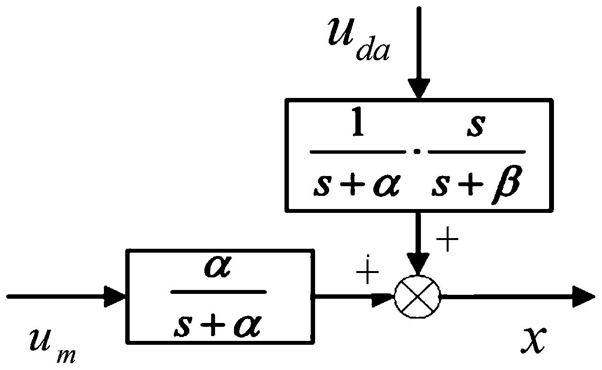
[0075] Step 3: Introduce a filter for estimating uncertainty and interference, and independently design it in the frequency domain to obtain the interference function in the frequency domain;

[0076] Step 4: By performing Lap...

specific Embodiment 2

[0118] Step one, combine figure 1 , by setting the parameters reasonably, the third-order LCL filter is simplified into a first-order system, and based on this, the mathematical model of the control system obtained by improving the traditional time-delay control is established. At this time, the circuit structure becomes LCCL, the original filter capacitor C is split into C1 and C2, and the feedback variable is changed from the grid-connected current to the current i12 between the parallel circuits. For the convenience of analysis, it is advisable to define L=L1+L2, L 1 =λL,L 2 =(1-λ)L,C=C 1 +C 2 ,

[0119] Step 2: Determine the setpoint tracking response from the reference model, and the state equation corresponding to the expected reference model can be expressed as: Among them, X m (t), U m (t), A m , B m Denote the desired state variable, desired control input, desired state matrix, and desired control matrix, respectively.

[0120] Step three, introducing a f...


PUM


Abstract

The invention is an uncertain parameter interference suppression method for an LCL filter grid-connected inverter. The LCL filter parameters are set, the third-order LCL filter is simplified to a first-order system, and a transfer function of a control system based on the traditional time-delay control is established; a state equation corresponding to the expected reference model is obtained, andaccording to the state equation corresponding to the expected reference model, a preliminary input expression is obtained; a filter for estimating uncertainty and interference is introduced to obtainan interference function in a frequency domain; Laplace transform is carried out on the preliminary input expression, a completed filter and an error feedback gain are independently designed in the frequency domain, a functional expression between control system output and input and errors is obtained, and the controller can thus suppress the interference. According to the LCL filter inverter uncertain parameter control method applicable to the power grid with various disturbances, suppression on external disturbances and parameter changes can be realized in a relatively simple manner.

Description

technical field [0001] The invention relates to the technical field of LCL filters, and relates to a method for suppressing uncertain parameter interference of LCL filter grid-connected inverters. Background technique [0002] In today's world, with the increasing scale of the power grid, many of its existing problems have also been magnified and received more and more attention. Ultra-large-scale power grids have high construction and operation and maintenance costs, and it is increasingly difficult to meet the high reliability and security requirements of customers with the rapid development of my country's economy. In addition, in today's society, the problems of environmental pollution and resource scarcity are becoming more and more imminent, and the concept of sustainable development vigorously promoted by our country has gradually become popular among the people. Therefore, renewable clean energy sources such as solar energy, wind energy, and tidal energy have receiv...

Claims


Application Information

Patent Timeline
IPC IPC(8): H02M1/12
CPCH02M1/12H02M1/123
Inventor 武健刘子栋张利刘同徐殿国
Owner HARBIN INST OF TECH
Learn More