Embedded expansion valve sealing structure in high-pressure oil tank of medical X-ray generator

A high-pressure fuel tank and sealing structure technology, applied in X-ray equipment, electrical components, etc., can solve problems such as poor sealing of high-pressure fuel tanks, untimely heat dissipation, and irregular fuel tanks. , The effect of convenient after-sales maintenance

Inactive Publication Date: 2019-10-22
NANNING YIJU MEDICAL ELECTRONICS
View PDF7 Cites 0 Cited by
  • Summary
  • Abstract
  • Description
  • Claims
  • Application Information

AI Technical Summary

Problems solved by technology

[0002] At present, medical X-ray generators are widely used in hospitals all over the country, and they are the most used equipment for various inspections and photographs; however, most of the current high-pressure fuel tanks of medical X-ray generators are welded and formed by steel plates, especially the fuel tanks. After the body is welded, the deformation is relatively large, and trachoma often occurs at the welding point, resulting in poor sealing of the assembled high-pressure fuel tank and frequent oil leakage. In the past, the expansion valve was fixed by more than a dozen screws, and the entire expansion valve was exposed. The outside of the fuel tank body makes the whole fuel tank not square and unsightly, and it is even more troublesome to replace the expansion valve. All the fixing screws must be removed, which is really time-consuming and laborious. Moreover, the high-pressure fuel tank generates a lot of heat when it is working, and the lack of timely heat dissipation seriously affects the whole set. The life and stability of the generator have greatly hindered the development of medical X-ray generators

Method used


Image

  • Embedded expansion valve sealing structure in high-pressure oil tank of medical X-ray generator
  • Embedded expansion valve sealing structure in high-pressure oil tank of medical X-ray generator
  • Embedded expansion valve sealing structure in high-pressure oil tank of medical X-ray generator

Examples


Embodiment

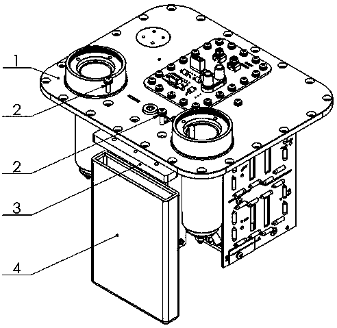
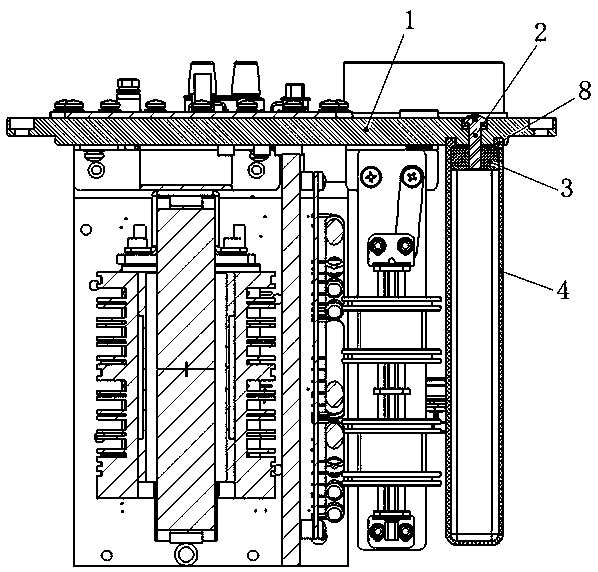
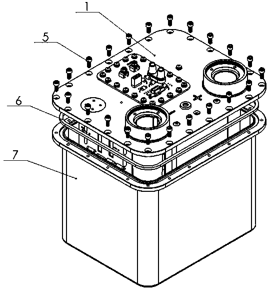
[0020] Such as Figure 1-3 As shown, a sealing structure of an embedded expansion valve in the high-pressure oil tank of a medical X-ray generator is mainly composed of a tank cover assembly 1, a cross-recessed combination screw 2, an expansion valve pressure plate 3, an expansion valve 4, an inner hexagon screw 5, and a square sealing ring 6 and the fuel tank body 7; the tank cover assembly 1 includes an integrally die-cast aluminum alloy tank cover and a circuit board, a high-voltage transformer and a filament transformer respectively fixed and assembled under the aluminum alloy tank cover; the expansion valve pressure plate 3 After being fixedly installed on the upper end of the expansion valve 4, it is fixedly installed under the aluminum alloy tank cover through the cross-recessed combination screw 2; the upper edge of the fuel tank body 7 is provided with a groove matching the square sealing ring 6, and the square After the sealing ring 6 is installed in the groove, the ...


PUM


Abstract

The invention discloses an embedded expansion valve sealing structure in a high-pressure oil tank of a medical X-ray generator. The embedded expansion valve sealing structure mainly comprises a tank cover component (1), a cross-shaped groove combined screw (2), an expansion valve pressing plate (3), an expansion valve (4), an inner hexagon screw (5), a square sealing ring (6), an oil tank body (7)and other parts. The embedded expansion valve sealing structure in the high-pressure oil tank of the medical X-ray generator has a sealing effect on the high-pressure oil tank of the medical X-ray generator, is influenced by the environment and heat generated when a machine works, can ensure that the whole high-pressure oil tank is in a sealing state through expansion caused by heat and contraction caused by cold of the expansion valve, has the simple structure, convenience in processing and assembling and the good sealing performance, and the aluminum alloy tank cover and the tank body are integrally formed by die-casting, so that the leakage problem and the heat dissipation problem of the tank body existing in welding seams of steel plates for welding the tank body are solved, and the service life of the high-pressure oil tank of the medical X-ray generator is greatly prolonged.

Description

technical field [0001] The invention belongs to the technical field of a sealing structure of an embedded expansion valve in a high-pressure oil tank of a medical X-ray generator. Background technique [0002] At present, medical X-ray generators are widely used in hospitals all over the country, and they are the most used equipment for various inspections and photographs; however, most of the current high-pressure fuel tanks of medical X-ray generators are welded and formed by steel plates, especially the fuel tanks. After the body is welded, the deformation is relatively large, and trachoma often occurs at the welding point, resulting in poor sealing of the assembled high-pressure fuel tank and frequent oil leakage. In the past, the expansion valve was fixed by more than a dozen screws, and the entire expansion valve was exposed. The outside of the fuel tank body makes the whole fuel tank not square and unsightly, and it is even more troublesome to replace the expansion va...

Claims


Application Information

Patent Timeline
IPC IPC(8): H05G1/04
CPCH05G1/04
Inventor 甘海波马培威
Owner NANNING YIJU MEDICAL ELECTRONICS
Why Eureka
Try Eureka