Safe and energy-saving cooking utensil

A cooking utensil and safety technology, applied in the field of safe and energy-saving cooking utensils, can solve the problems of large amount of steam, rising water temperature, pollution of the kitchen environment, etc., and achieve the effect of good cooling effect

Active Publication Date: 2019-10-25
JOYOUNG CO LTD
View PDF7 Cites 4 Cited by
  • Summary
  • Abstract
  • Description
  • Claims
  • Application Information

AI Technical Summary

Problems solved by technology

[0002] Rice cookers and pressure cookers are essential items in the kitchen, and the taste of the food they cook is unanimously recognized by everyone. In order to improve the cooking effect and further improve the food effect, a rice cooker with steam heating has appeared in the industry. This steam-heated rice cooker produces The amount of steam is larger and more, during the cooking process, it needs to discharge more steam, which may cause the risk of polluting the kitchen environ...

Method used


Image

  • Safe and energy-saving cooking utensil
  • Safe and energy-saving cooking utensil
  • Safe and energy-saving cooking utensil

Examples


Embodiment 1

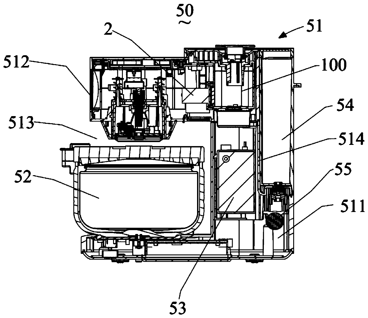
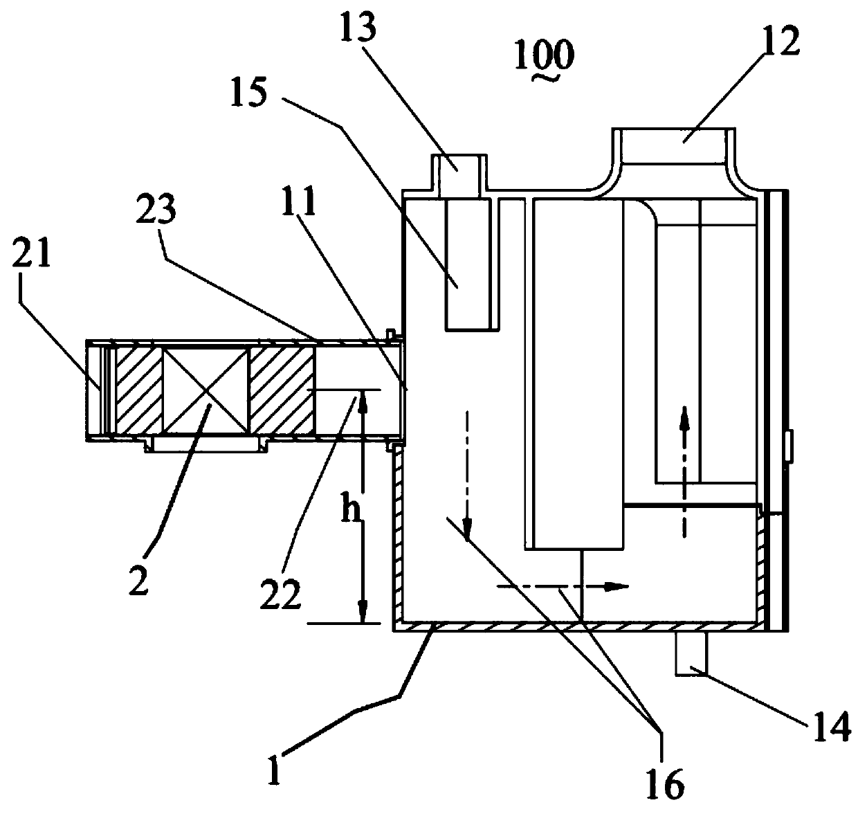
[0034] see figure 1 , figure 2 As shown, the first embodiment of a safe and energy-saving cooking appliance 50 according to the present invention includes a main body 51, a pot body 52, and a steam generator 53 arranged in the body. The pot body 52 is placed in the body 51. The steam generator 53 communicates with the inside of the pot body to supply steam to heat the food in the pot body. A steam condensing device 100 connected to the pot body to condense steam is also provided in the body. The steam condensing device includes a cooling mixing chamber 1, an accelerated steam cooling The fan 2 of the cooling mixing chamber 1 is provided with an air inlet 11, an exhaust port 12, a first steam inlet 13, and a drain port 14. The first steam inlet 13 guides steam into the cooling mixing chamber 1, and the drain port 14 is arranged in the cooling mixing chamber. Bottom of chamber 1. The fan 2 is provided with an air inlet 21 and an air outlet 22. The cold air blown out by the ai...

Embodiment 2

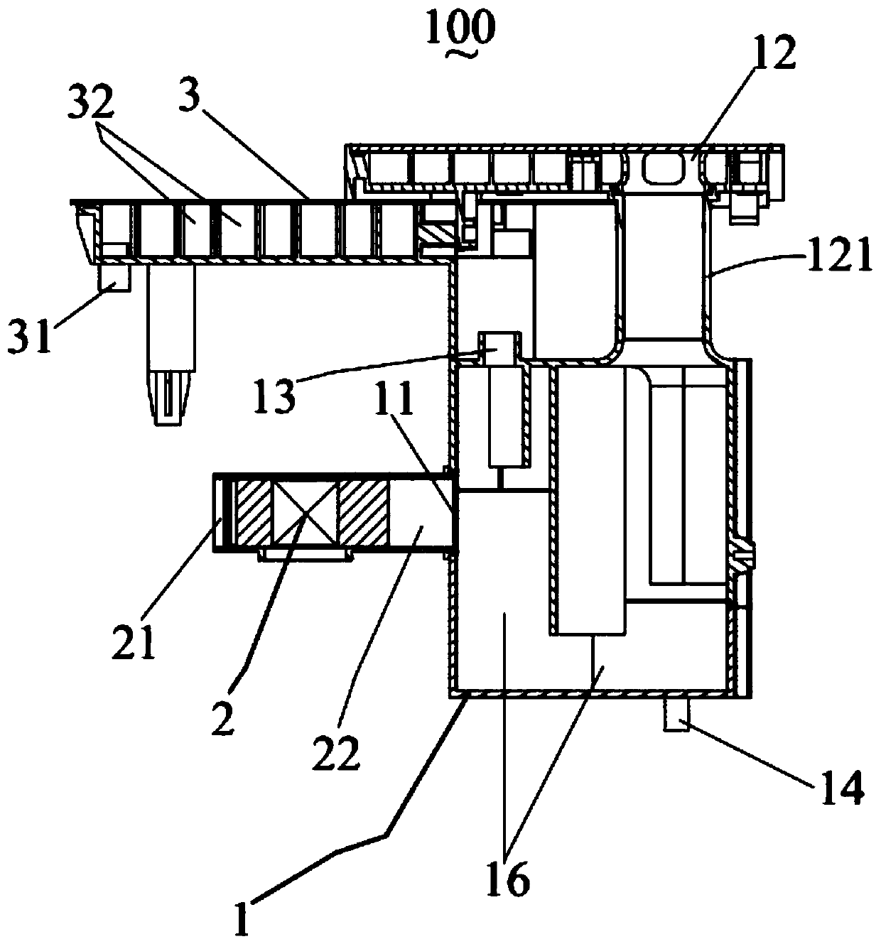
[0059] see image 3 As shown, the second embodiment of the present invention adds a cooling buffer chamber 3 on the basis of Embodiment 1, the cooling buffer chamber is arranged at the front end of the first steam inlet 13, and the cooling buffer chamber is provided with a second steam inlet 31, To introduce steam into the cooling buffer chamber 3 , the first steam inlet 13 communicates with the cooling buffer chamber 3 to introduce the steam in the cooling buffer chamber into the cooling mixing chamber 1 .

[0060] In this embodiment, the cooling buffer chamber 3 is arranged at the front end of the first steam inlet 13 to perform preliminary cooling and buffer reserve for the steam entering the cooling mixing chamber, so as to avoid the injection of cold air into the cooling mixing chamber and affect the front end. Steam heating or front-end heating effect.

[0061] As an improved embodiment, the cooling and buffer chamber 3 is also provided with a drain hole (not shown in t...

Embodiment 3

[0069] see Figure 4 As shown, the fourth embodiment of the present invention is improved on the basis of the first embodiment. The cooling mixing chamber 1 includes a first mixing part 10 formed by a steam introduction pipe 4, and a second mixing part 20. The first steam The inlet is the boundary between the steam introduction pipe and the first mixing part. That is to say, a third steam introduction port 41 is provided at the front end of the steam introduction pipeline for steam introduction flow, and the rear end of the steam introduction pipeline 4 forms the first mixing part 10 of the cooling mixing chamber, and the mixing, exhaust, structures such as drainage.

[0070] As a preferred embodiment, the shape of the second mixing part is consistent with the first embodiment. The air inlet is arranged in the first mixing part 10 . In this embodiment, the steam leading pipe is used to form a part of the cooling mixing chamber, which enlarges the effective cooling path of t...


PUM


Abstract

The invention discloses a safe and energy-saving cooking utensil. The steam generator comprises a body, a pot body and a steam generator body arranged in the body. The pot body is placed in the body.The steam generator is communicated with the interior of the pot body to supply steam to heat food in the pot body. The safe and energy-saving cooking utensil is characterized in that a steam condensing device which is communicated with the pot body to condense steam is also arranged in the body. The steam condensing device comprises a cooling mixing cavity, and a fan for accelerating the steam cooling. The cooling mixing cavity is provided with an air inlet, an air outlet, a first steam inlet and a water outlet. The steam is introduced into the cooling mixing cavity through the first steam inlet. The water outlet is formed in the bottom of the cooling mixing cavity. The fan is provided with an air suction port and an air outlet. The cold air blown out of the air outlet enters the coolingmixing cavity through the air inlet to be mixed with steam for cooling. The cooled air is exhausted out of the condensing device through the air outlet. The water outlet is directly or indirectly communicated with the steam generator to heat condensed water to form steam. The cooling effect can be guaranteed, and the cooling efficiency is improved.

Description

technical field [0001] The invention relates to the field of kitchen appliances, in particular to a safe and energy-saving cooking appliance. Background technique [0002] Rice cookers and pressure cookers are essential items in the kitchen, and the taste of the food they cook is unanimously recognized by everyone. In order to improve the cooking effect and further improve the food effect, a rice cooker with steam heating has appeared in the industry. This steam-heated rice cooker produces The amount of steam is larger and more, during the cooking process, it needs to discharge more steam, which may cause the risk of polluting the kitchen environment, and may also burn the user. [0003] In order to solve the above problems, the practice in the industry is to set up a water-cooled box to introduce steam into cold water to cool and collect condensed water. This structure will cause a significant rise in water temperature and poor cooling effect for long-term cooking, and the ...

Claims


Application Information

Patent Timeline
IPC IPC(8): A47J27/04A47J36/38
CPCA47J27/04A47J36/38A47J2027/043
Inventor 朱泽春于凌振邱雄杰
Owner JOYOUNG CO LTD
Why Eureka
Try Eureka