Convenient-to-use lower limb exercising device for gynaecology and obstetrics

A sports device, obstetrics and gynecology technology, applied in medical science, medical transportation, passive exercise equipment, etc., can solve problems such as arm fatigue and soreness of accompanying personnel, increase the burden of accompanying personnel, and adverse effects of pregnant women, etc., and achieve easy maintenance and repair , Avoid arm fatigue and soreness, the effect of simple structure

Inactive Publication Date: 2019-10-25
魏双燕
13 Cites 1 Cited by

AI-Extracted Technical Summary

Problems solved by technology

[0002] The Department of Obstetrics and Gynecology mainly studies the etiology, pathology, diagnosis and prevention of female reproductive organ diseases, the physiological and pathological changes of pregnancy and childbirth, the prevention, diagnosis and treatment of high-risk pregnancy and dystocia, female reproductive endocrinology, family planning and women's health care, etc., in order to protect women Physical and reproductive health and the prevention and treatment of various obstetrics and gynecology diseases play an important role. Obstetrics and gynecology are not only closely related to clinical sciences such as surgery, internal medicine, and pediatrics, but also require basic knowledg...

Method used

At this moment, the first locking tooth 55 and the second locking tooth 56 block the double-sided rack 13, thereby the first swinging plate 3 can be fixed, and when the first swinging plate 3 needs to be swung, the first swinging plate 3 can be first The first pin rod 52 is pulled out from the first pin hole 141, then the movable plate 51 is pulled forward, and the first latch 55 and the second latch 56 are removed from the double-sided rack 13, when When the second pin rod 53 moved forward to the position where the second pin hole 151 was located, the second pin rod 53 could be inserted downward into the second pin hole 151, thereby the movable plate 51, the first bayonet 55, the second The locking teeth 56 are fixed, and then the first...

Abstract

The invention relates to a lower limb exercising device for gynaecology and obstetrics, in particular to a convenient-to-use lower limb exercising device for the gynaecology and obstetrics, aiming toavoid fatigue and soreness of arms of nursing workers and reduce burdens of the nursing workers. The convenient-to-use lower limb exercising device for the gynaecology and obstetrics comprises a base,a long rotating shaft, a first swinging plate, a second swinging plate, a first arc-shaped carrying plate, a second arc-shaped carrying plate and the like. A large groove is formed in the top of thebase, and the long rotating shaft is rotatably connected to the right portion of the base. The convenient-to-use lower limb exercising device for the gynaecology and obstetrics has the advantages thatthe nursing workers do not need to massage lower limbs of pregnant women by hands, the lower limbs of the pregnant women can be prevented from swelling, the fatigue and soreness of the arms of the nursing workers can be avoided, and the burdens of the nursing workers can be reduced, so that the nursing workers can take care of the pregnant women more comprehensively.

Application Domain

Chiropractic devicesNursing beds +1

Technology Topic

Lower limb exercisesObstetrics gynaecology +1

Image

  • Convenient-to-use lower limb exercising device for gynaecology and obstetrics
  • Convenient-to-use lower limb exercising device for gynaecology and obstetrics
  • Convenient-to-use lower limb exercising device for gynaecology and obstetrics

Examples

  • Experimental program(4)

Example Embodiment

[0014] Example 1
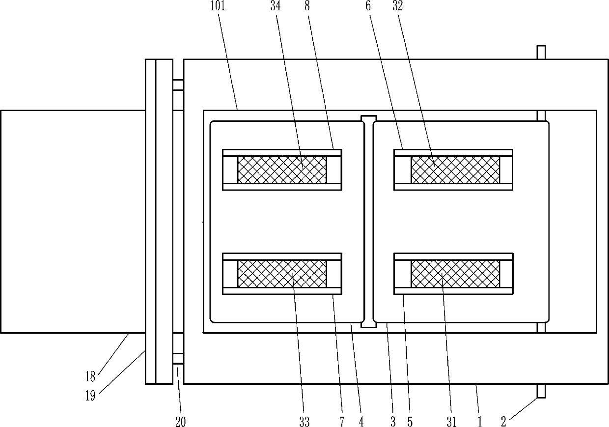
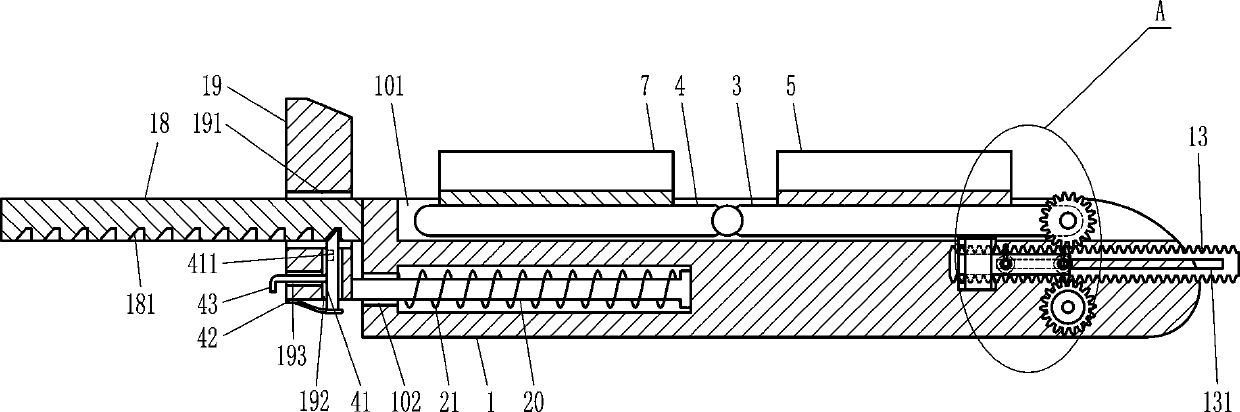
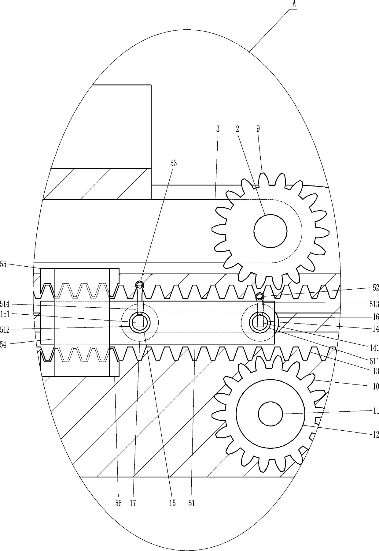
[0015] An easy-to-use lower limb exercise device for obstetrics and gynecology, such as Figure 1-3 As shown, it includes a base 1, a long rotating shaft 2, a first swing plate 3, a second swing plate 4, a first arc-shaped pallet 5, a second arc-shaped pallet 6, a third arc-shaped pallet 7, and Four-curved support plate 8, first gear 9, second gear 10, large rotating shaft 11, rotating wheel 12, double-sided rack 13, first support rod 14, second support rod 15, first stop plate 16, The second stop plate 17, the large support plate 18, the large wedge block 19, the guide rod 20 and the large spring 21, the top of the base 1 is opened with a large groove 101, the long rotating shaft 2 is connected to the right part of the base 1 for long rotation The shaft 2 is located in the large groove 101, the right end of the first swing plate 3 is fixedly sleeved on the long rotating shaft 2, the second swing plate 4 is located on the left side of the first swing plate 3, the second swing plate 4 and the first swing plate 3 articulated connection, the first swing plate 3 and the second swing plate 4 are both located in the large groove 101, the first swing plate 3 and the second swing plate 4 are in contact with the base 1, and the top of the first swing plate 3 is connected with The first arc-shaped pallet 5 and the second arc-shaped pallet 6, the first arc-shaped pallet 5 and the second arc-shaped pallet 6 are all connected to the first swing plate 3 by welding, and the second arc-shaped pallet The plate 6 is located directly behind the first arc-shaped pallet 5, the top of the second swinging plate 4 is connected with the third arc-shaped pallet 7 and the fourth arc-shaped pallet 8, and the fourth arc-shaped pallet 8 is located in the third arc. Right behind the arc-shaped pallet 7, the third arc-shaped pallet 7 corresponds to the first arc-shaped pallet 5, the fourth arc-shaped pallet 8 corresponds to the second arc-shaped pallet 6, and the front end of the long rotating shaft 2 Connected to the first gear 9, the first gear 9 is located in front of the base 1, the second gear 10 is located directly below the first gear 9, the second gear 10 is fixedly sleeved on the large rotating shaft 11, the rear end of the large rotating shaft 11 Rotatingly connected with the base 1, the front end of the large rotating shaft 11 is connected with a rotating wheel 12, the large rotating shaft 11 is connected to the rotating wheel 12 by welding, and the double-sided rack 13 is located between the first gear 9 and the second gear 10 , The first gear 9 and the second gear 10 are both meshed with the double-sided rack 13, the double-sided rack 13 is provided with a long sliding groove 131, and the front side of the base 1 is connected with a first supporting rod 14 and a second supporting rod 15 , The first support rod 14 is located on the right side of the second support rod 15, the first support rod 14 and the second support rod 15 are both located in the long chute 131, the first support rod 14 and the second support rod 15 are both double-sided The rack 13 is in contact, the first stop plate 16 is fixed and sleeved on the first support rod 14, the second stop plate 17 is fixed and sleeved on the second support rod 15, the first stop plate 16 and the second stop plate 17 are both located in the double In front of the face rack 13, the first stop plate 16 and the second stop plate 17 are in contact with the double-sided rack 13, the first support rod 14 is provided with a first pin hole 141, and the first pin hole 141 is located in the first gear In the front of the disk 16, the second support rod 15 has a second pin hole 151, the second pin hole 151 is located in front of the first pin hole 141, the upper left side of the base 1 is connected with a large support plate 18, and the base 1 is connected by welding The large pallet 18 is connected to the large pallet 18, the bottom of the large pallet 18 is provided with a spine groove 181, the large wedge block 19 is located on the left side of the base 1, the large wedge block 19 is provided with a large rectangular slot 191, and the large pallet 18 is located on the large rectangle In the groove 191, the large pallet 18 is in contact with the large wedge block 19, the large wedge block 19 is provided with a small rectangular slot 192, the small rectangular slot 192 is located below the large rectangular slot 191, and the small rectangular slot 192 communicates with the large rectangular slot 191 , The large wedge block 19 is provided with a long slot 193, the long slot 193 is located on the left side of the small rectangular slot 192, the long slot 193 communicates with the small rectangular slot 192, the right side of the big wedge block 19 is connected with a guide rod 20, The guide rod 20 is located below the large pallet 18, the base 1 is provided with a guide groove 102, the guide groove 102 is located below the large groove 101, the guide rod 20 is slidably located in the guide groove 102, and the large spring 21 is sleeved on the guide rod 20 , The large spring 21 is located in the guide groove 102.

Example Embodiment

[0016] Example 2
[0017] An easy-to-use lower limb exercise device for obstetrics and gynecology, such as Figure 1-3 As shown, it includes a base 1, a long rotating shaft 2, a first swing plate 3, a second swing plate 4, a first arc-shaped pallet 5, a second arc-shaped pallet 6, a third arc-shaped pallet 7, and Four-curved support plate 8, first gear 9, second gear 10, large rotating shaft 11, rotating wheel 12, double-sided rack 13, first support rod 14, second support rod 15, first stop plate 16, The second stop plate 17, the large support plate 18, the large wedge block 19, the guide rod 20 and the large spring 21, the top of the base 1 is provided with a large groove 101, the long rotating shaft 2 is connected to the right part of the base 1 for long rotation The shaft 2 is located in the large groove 101, the right end of the first swing plate 3 is fixedly sleeved on the long rotating shaft 2, the second swing plate 4 is located on the left side of the first swing plate 3, the second swing plate 4 and the first swing plate 3 hinged connection, the first swing plate 3 and the second swing plate 4 are both located in the large groove 101, the first swing plate 3 and the second swing plate 4 are in contact with the base 1, and the top of the first swing plate 3 is connected with The first arc-shaped pallet 5 and the second arc-shaped pallet 6, the second arc-shaped pallet 6 is located directly behind the first arc-shaped pallet 5, and the top of the second swing plate 4 is connected with a third arc-shaped pallet 7 and the fourth arc pallet 8, the fourth arc pallet 8 is located directly behind the third arc pallet 7, the third arc pallet 7 corresponds to the first arc pallet 5, and the fourth arc The pallet 8 corresponds to the second arc pallet 6. The front end of the long rotating shaft 2 is connected with a first gear 9. The first gear 9 is located in front of the base 1, and the second gear 10 is located directly below the first gear 9. , The second gear 10 is fixedly sleeved on the large rotating shaft 11, the rear end of the large rotating shaft 11 is rotatably connected with the base 1, the front end of the large rotating shaft 11 is connected with the rotating wheel 12, and the double-sided rack 13 is located between the first gear 9 and Between the second gears 10, the first gear 9 and the second gear 10 are both meshed with a double-sided rack 13. The double-sided rack 13 is provided with a long sliding groove 131, and a first supporting rod 14 is connected to the front side of the base 1 And the second support rod 15, the first support rod 14 is located on the right side of the second support rod 15, the first support rod 14 and the second support rod 15 are both located in the long chute 131, the first support rod 14 and the second support rod The rods 15 are in contact with the double-sided rack 13, the first stop plate 16 is fixed and sleeved on the first support rod 14, the second stop plate 17 is fixed and sleeved on the second support rod 15, the first stop plate 16 and the second support rod The stop plates 17 are all located in front of the double-sided rack 13, the first stop plate 16 and the second stop plate 17 are in contact with the double-sided rack 13, the first supporting rod 14 is provided with a first pin hole 141, and a first pin The hole 141 is located in front of the first stop plate 16, the second support rod 15 has a second pin hole 151, the second pin hole 151 is located in front of the first pin hole 141, and the upper left side of the base 1 is connected with a large support plate 18 , The bottom of the large pallet 18 is provided with a spine groove 181, the large wedge block 19 is located on the left side of the base 1, the large wedge block 19 is provided with a large rectangular groove 191, the large pallet 18 is located in the large rectangular groove 191, and the large pallet 18 In contact with the large wedge block 19, the large wedge block 19 is provided with a small rectangular slot 192. The small rectangular slot 192 is located below the large rectangular slot 191. The small rectangular slot 192 communicates with the large rectangular slot 191. The block 19 is provided with a long slot 193. The long slot 193 is located on the left side of the small rectangular slot 192. The long slot 193 communicates with the small rectangular slot 192. The right side of the large wedge block 19 is connected with a guide rod 20, which is a guide rod 20. Located below the large pallet 18, the base 1 is provided with a guide groove 102, the guide groove 102 is located below the large groove 101, the guide rod 20 is slidably located in the guide groove 102, the large spring 21 is sleeved on the guide rod 20, and the large spring 21 is located in the guide groove 102.
[0018] It also includes a first rubber cushion 31, a second rubber cushion 32, a third rubber cushion 33, and a fourth rubber cushion 34. The inner bottom of the first arc-shaped pallet 5 is connected with a first rubber cushion 31, The inner bottom of the second arc-shaped pallet 6 is connected with a second rubber cushion 32, the inner bottom of the third arc-shaped pallet 7 is connected with a third rubber cushion 33, and the inner bottom of the fourth arc-shaped pallet 8 is connected with The fourth rubber cushion 34.

Example Embodiment

[0019] Example 3
[0020] An easy-to-use lower limb exercise device for obstetrics and gynecology, such as Figure 1-3 As shown, it includes a base 1, a long rotating shaft 2, a first swing plate 3, a second swing plate 4, a first arc-shaped pallet 5, a second arc-shaped pallet 6, a third arc-shaped pallet 7, and Four-curved support plate 8, first gear 9, second gear 10, large rotating shaft 11, rotating wheel 12, double-sided rack 13, first support rod 14, second support rod 15, first stop plate 16, The second stop plate 17, the large support plate 18, the large wedge block 19, the guide rod 20 and the large spring 21, the top of the base 1 is provided with a large groove 101, the long rotating shaft 2 is connected to the right part of the base 1 for long rotation The shaft 2 is located in the large groove 101, the right end of the first swing plate 3 is fixedly sleeved on the long rotating shaft 2, the second swing plate 4 is located on the left side of the first swing plate 3, the second swing plate 4 and the first swing plate 3 hinged connection, the first swing plate 3 and the second swing plate 4 are both located in the large groove 101, the first swing plate 3 and the second swing plate 4 are in contact with the base 1, and the top of the first swing plate 3 is connected with The first arc-shaped pallet 5 and the second arc-shaped pallet 6, the second arc-shaped pallet 6 is located directly behind the first arc-shaped pallet 5, and the top of the second swing plate 4 is connected with a third arc-shaped pallet 7 and the fourth arc pallet 8, the fourth arc pallet 8 is located directly behind the third arc pallet 7, the third arc pallet 7 corresponds to the first arc pallet 5, and the fourth arc The pallet 8 corresponds to the second arc pallet 6. The front end of the long rotating shaft 2 is connected with a first gear 9. The first gear 9 is located in front of the base 1, and the second gear 10 is located directly below the first gear 9. , The second gear 10 is fixedly sleeved on the large rotating shaft 11, the rear end of the large rotating shaft 11 is rotatably connected with the base 1, the front end of the large rotating shaft 11 is connected with the rotating wheel 12, and the double-sided rack 13 is located between the first gear 9 and Between the second gears 10, the first gear 9 and the second gear 10 are both meshed with a double-sided rack 13. The double-sided rack 13 is provided with a long sliding groove 131, and a first supporting rod 14 is connected to the front side of the base 1 And the second support rod 15, the first support rod 14 is located on the right side of the second support rod 15, the first support rod 14 and the second support rod 15 are both located in the long chute 131, the first support rod 14 and the second support rod The rods 15 are in contact with the double-sided rack 13, the first stop plate 16 is fixed and sleeved on the first support rod 14, the second stop plate 17 is fixed and sleeved on the second support rod 15, the first stop plate 16 and the second support rod The stop plates 17 are all located in front of the double-sided rack 13, the first stop plate 16 and the second stop plate 17 are in contact with the double-sided rack 13, the first supporting rod 14 is provided with a first pin hole 141, and a first pin The hole 141 is located in front of the first stop plate 16, the second support rod 15 has a second pin hole 151, the second pin hole 151 is located in front of the first pin hole 141, and the upper left side of the base 1 is connected with a large support plate 18 , The bottom of the large pallet 18 is provided with a spine groove 181, the large wedge block 19 is located on the left side of the base 1, the large wedge block 19 is provided with a large rectangular groove 191, the large pallet 18 is located in the large rectangular groove 191, and the large pallet 18 In contact with the large wedge block 19, the large wedge block 19 is provided with a small rectangular slot 192. The small rectangular slot 192 is located below the large rectangular slot 191. The small rectangular slot 192 communicates with the large rectangular slot 191. The block 19 is provided with a long slot 193. The long slot 193 is located on the left side of the small rectangular slot 192. The long slot 193 communicates with the small rectangular slot 192. The right side of the large wedge block 19 is connected with a guide rod 20, which is a guide rod 20. Located below the large pallet 18, the base 1 is provided with a guide groove 102, the guide groove 102 is located below the large groove 101, the guide rod 20 is slidably located in the guide groove 102, the large spring 21 is sleeved on the guide rod 20, and the large spring 21 is located in the guide groove 102.
[0021] It also includes a first rubber cushion 31, a second rubber cushion 32, a third rubber cushion 33, and a fourth rubber cushion 34. The inner bottom of the first arc-shaped pallet 5 is connected with a first rubber cushion 31, The inner bottom of the second arc-shaped pallet 6 is connected with a second rubber cushion 32, the inner bottom of the third arc-shaped pallet 7 is connected with a third rubber cushion 33, and the inner bottom of the fourth arc-shaped pallet 8 is connected with The fourth rubber cushion 34.
[0022] It also includes a large spine block 41, an arc-shaped leaf spring 42 and a large pin 43. The large spine block 41 is slidably located in the small rectangular groove 192, the upper end of the large spine block 41 is located in the spine groove 181, and the large spine block 41 and the spine The slots 181 are matched, the upper left part of the big spine block 41 is provided with a small slot 411, the bottom of the big wedge block 19 is connected with an arc-shaped leaf spring 42, and the big wedge block 19 is connected with the arc-shaped leaf spring 42 by welding. , The arc-shaped leaf spring 42 is located below the large spine block 41, the arc-shaped leaf spring 42 is in contact with the large spine block 41, the large pin rod 43 is slidably located in the long slot 193, and the large pin rod 43 is opposite to the large spine block 41 Upon contact, the large pin 43 is matched with the small slot 411.

PUM

no PUM

Description & Claims & Application Information

We can also present the details of the Description, Claims and Application information to help users get a comprehensive understanding of the technical details of the patent, such as background art, summary of invention, brief description of drawings, description of embodiments, and other original content. On the other hand, users can also determine the specific scope of protection of the technology through the list of claims; as well as understand the changes in the life cycle of the technology with the presentation of the patent timeline. Login to view more.

Similar technology patents

Catheter kit for burrow

InactiveCN1780599AReduce the burden on
Owner:SUMITOMO BAKELITE CO LTD +1

Method for forwarding data message and route device

ActiveCN102611619AReduce the burden onImprove scalability and compatibility
Owner:ZTE CORP
Why Eureka
Try Eureka