Hardware pipe stock automatic punching machine

An automatic punching and pipe technology, applied in the field of pipe processing, can solve the problems of high labor intensity, low production efficiency and high labor cost, and achieve the effect of satisfying mass production, convenient and fast expansion and contraction, and reducing manual operation.

Active Publication Date: 2019-10-25
东莞市天誉箱包配件有限公司
View PDF7 Cites 23 Cited by
  • Summary
  • Abstract
  • Description
  • Claims
  • Application Information

AI Technical Summary

Problems solved by technology

[0003] In the pipe punching process in the prior art, usually only one pipe can be punched in each operation, the production efficiency is low, and the pipes are usually manually placed on the mold during operation For punching, after the pipe is punched, the pipe is manually removed from the mold, and the manual loading and unloading of the pipe is not only labor-intensive and labor-intensive, but also leads to poor positioning accuracy of the workpiece , it cannot be connected with the assembly line, and cannot meet the requirements of large-scale and mass production of enterprises, so it needs to be improved

Method used


Image

  • Hardware pipe stock automatic punching machine
  • Hardware pipe stock automatic punching machine
  • Hardware pipe stock automatic punching machine

Examples


Embodiment Construction

[0039] The present invention will be described in further detail below in conjunction with the accompanying drawings.

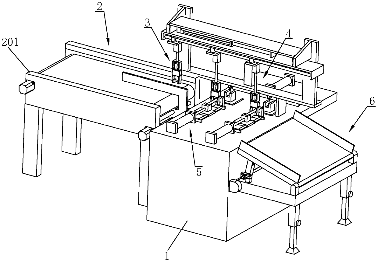
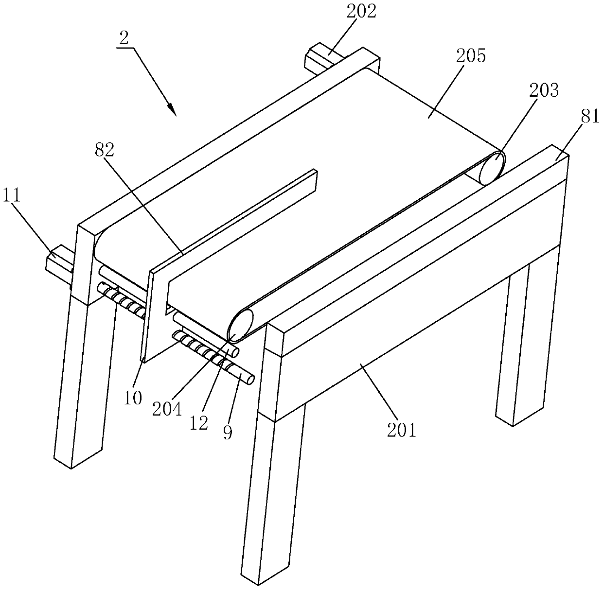
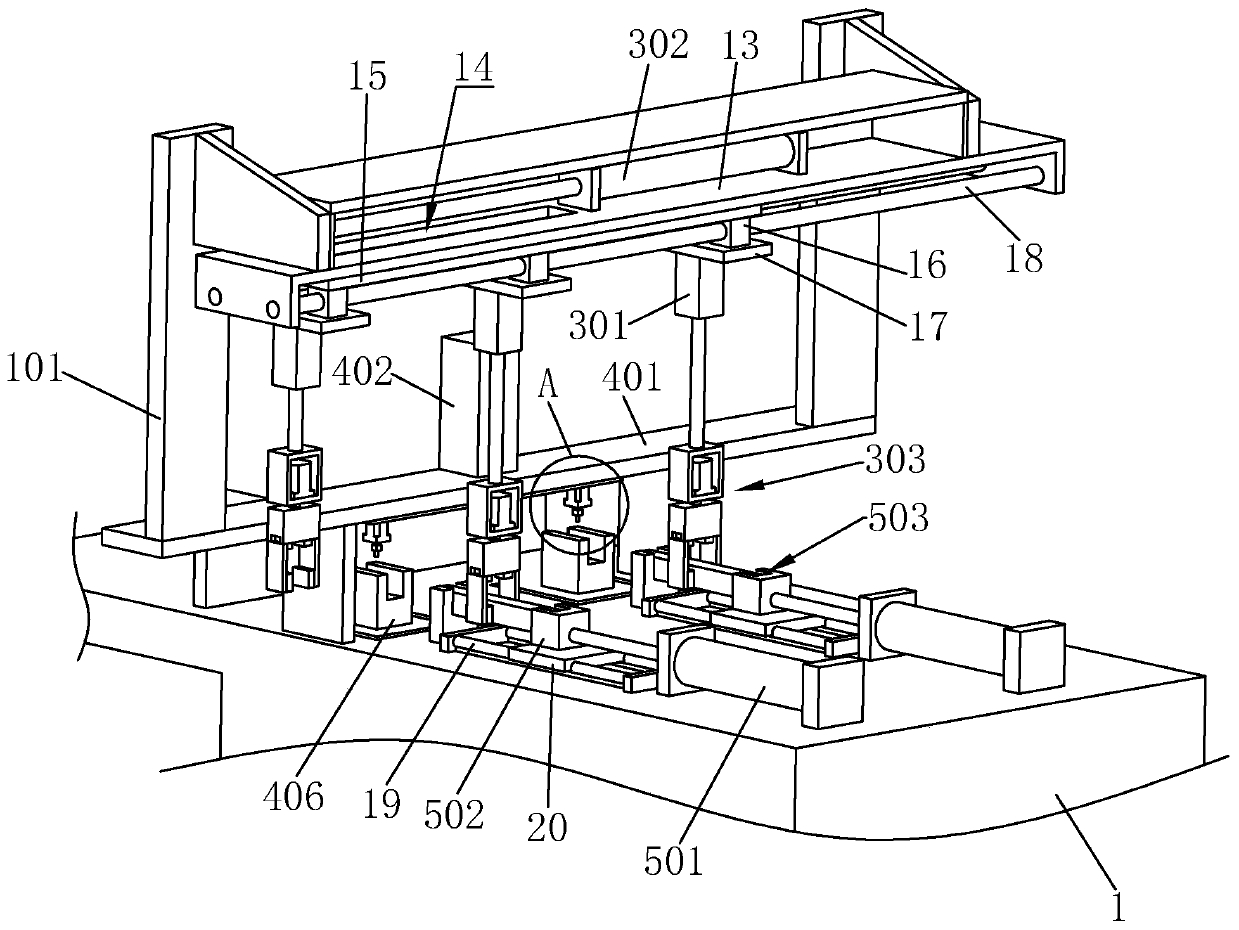
[0040] A metal pipe automatic punching machine, refer to figure 1 , including workbench 1 and several sets of feeding mechanisms 2 installed on the workbench 1, clamping mechanism 3 for clamping and moving the pipe on the feed mechanism 2, and punching and forming for the pipe used in conjunction with the clamping mechanism 3 The forming mechanism 4, the pushing mechanism 5 for pushing the pipe to move to the forming mechanism 4 for processing, the receiving mechanism 6 for collecting the formed pipe, and the cleaning mechanism 7 for collecting the waste after punching. At the same time, the pusher mechanism 5 is equipped with a receiving part for the horizontal placement of the pipes, and the pipes are arranged in turn on the feeding mechanism 2 for feeding, and the pipes are moved from the feeding mechanism 2 to the receiving part through the clamping mecha...


PUM


Abstract

The invention relates to the technical field of pipe stock machining, in particular to a hardware pipe stock automatic punching machine. According to key points of the technical scheme, the hardware pipe stock automatic punching machine comprises a working table, a plurality of feeding mechanisms arranged on the working table, a clamping mechanism for clamping and moving pipe stocks on the feedingmechanism, a forming mechanism, a pushing mechanism, a collecting mechanism and a cleaning mechanism, wherein the forming mechanism is used in cooperation with the clamping mechanism and carries outpunching forming on the pipe stocks, the pushing mechanism pushes the pipe stocks to move to the forming mechanism for machining, the collecting mechanism collects the formed pipe stocks, and the cleaning mechanism collects scraps after punching. A receiving portion for transversely placing the pipe stocks is arranged on the pushing mechanism. The pipe stocks are sequentially arranged on the feeding mechanism to be fed. By means of the clamping mechanism, the pipe stocks are moved to the receiving portion from the feeding mechanism, the pushing mechanism pushes the pipe stocks to the forming mechanism to be punched and formed, and the formed pipe stocks are collected through the collecting mechanism. The punching machine reduces manual operation, the production efficiency is high, the punching machine is applicable to butt joint of an assembly line, and the requirement for batch production is met.

Description

technical field [0001] The invention relates to the technical field of pipe processing, in particular to an automatic punching machine for metal pipes. Background technique [0002] Pipes or profiles are widely used in construction, decoration, and various product processing and production. In order to meet various needs, pipes need to be cut, bent, welded, and drilled. The hole is not small; one requires a variety of hole types, the second requires the coordination and unity of the holes on the same pipe at a certain angle, the third requires the speed and quality of the hole, and the four requires the hole distance of the hole. Accuracy and multi-dimensionality. [0003] In the pipe punching process in the prior art, usually only one pipe can be punched in each operation, the production efficiency is low, and the pipes are usually manually placed on the mold during operation For punching, after the pipe is punched, the pipe is manually removed from the mold, and the manu...

Claims


Application Information

Patent Timeline
Patent Type & Authority Applications(China)
IPC IPC(8): B21D28/34B21D28/28B21D43/10B21D43/12B21D43/02B08B5/04
CPCB08B5/04B21D28/28B21D28/34B21D43/027B21D43/105B21D43/12
Inventor 李佩兰
Owner 东莞市天誉箱包配件有限公司
Why Eureka
Try Eureka