Rotary tiller tool shaft tool magazine automatic welding machine

A technology of automatic welding machine and rotary tiller, which is applied in the direction of welding equipment, auxiliary welding equipment, welding/cutting auxiliary equipment, etc. It can solve the problem that the knife magazine cannot be sent to the designated position of the knife shaft, the welding angle change cannot be satisfied, and the welding quality cannot be solved. Can not be guaranteed and other problems, to achieve the effect of reducing the labor intensity of workers, achieving firm welding, and improving welding quality

Active Publication Date: 2021-10-19
HUAIYIN INSTITUTE OF TECHNOLOGY
View PDF0 Cites 0 Cited by
  • Summary
  • Abstract
  • Description
  • Claims
  • Application Information

AI Technical Summary

Problems solved by technology

[0003] For the welding of the rotary tiller cutter shaft tool magazine, the traditional manual welding method has a huge workload, low efficiency, and the welding quality cannot be guaranteed
In principle, the existing automatic welding machine can realize the welding between the tool shaft and the tool magazine, but most of the welding between the tool shaft and the tool magazine is not uniform, and there are even many gaps left, the degree of firmness is poor, and when it breaks during use happened
This is because the contact surface between the tool magazine and the tool shaft is arc-shaped, and the tool magazine supply device of the existing automatic welding machine cannot smoothly send the tool magazine to the designated position of the knife shaft. At the same time, the angle of the welding torch needs to be adjusted and changed at different positions. The angle of the existing automatic welding machine welding torch is generally fixed, which cannot meet the technological requirements of the angle change during welding. At the same time, a large number of manual assistance is required in welding.

Method used


Image

  • Rotary tiller tool shaft tool magazine automatic welding machine
  • Rotary tiller tool shaft tool magazine automatic welding machine
  • Rotary tiller tool shaft tool magazine automatic welding machine

Examples


Embodiment Construction

[0017] The specific implementation manners of the present invention will be described in detail below in conjunction with the accompanying drawings.

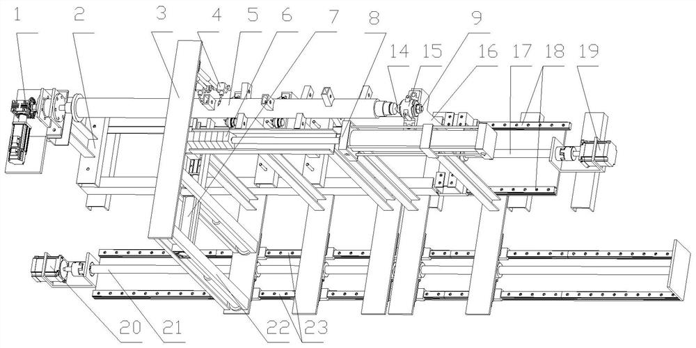
[0018] Such as figure 1 As shown, the rotary cultivator cutter shaft automatic welding machine of the present invention includes a main frame 2, a rotary indexing mechanism 1 fixedly installed on the upper left platform of the main frame 2, and a cutter shaft slidably connected to the right side of the main frame 2 Jacking mechanism 9, a transverse movement mechanism 3 located in the middle of the main frame 2 and capable of moving back and forth along the direction of the cutter shaft 5, the transverse movement mechanism 3 is provided with a knife magazine transverse feed mechanism 8, a knife magazine longitudinal feed mechanism 7 and a welding mechanism 4 .

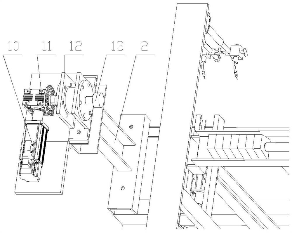
[0019] Such as figure 2 As shown, the rotary indexing mechanism 1 sequentially includes an indexing servo motor 10, a reduction box 11, and an indexing spline shaft 13...


PUM


Abstract

The invention relates to an automatic welding machine for rotary cultivator cutter shaft and cutter magazine, which includes a main frame, on which a rotary indexing mechanism for controlling the rotation of the cutter shaft, a cutter shaft tightening mechanism, and a reciprocating mechanism capable of reciprocating along the direction of the cutter shaft are arranged on the main frame. A moving transverse movement mechanism, which is provided with a knife magazine transverse feed mechanism for storing and supplying the knife magazine, a knife magazine longitudinal feed mechanism and a welding mechanism for pushing the knife magazine to the designated position of the knife shaft, The welding mechanism is equipped with a welding torch that can adjust the welding angle. The invention can realize the welding requirements of different angles of the welding torch, so that the knife magazine and the knife shaft are completely welded, and the welding is uniform, the firmness is good, the welding quality can be effectively improved, and the adaptability is wider.

Description

technical field [0001] The invention belongs to the technical field of agricultural machinery equipment, and in particular relates to an automatic welding machine for a rotary cultivator cutter shaft and cutter magazine. Background technique [0002] In recent years, with the continuous deepening of agricultural mechanization, rotary tillers have been widely used in land cultivation, and the market demand and annual output are both large. The knife shaft is the main part of the rotary tiller. A certain number of knife magazines are welded on the knife shaft according to a certain rotation angle and spacing, and the rotary tiller is loaded into the knife magazine according to the needs of forward rotation and reverse rotation. [0003] For the welding of the rotary tiller cutter shaft tool magazine, the traditional manual welding method has a huge workload, low efficiency, and the welding quality cannot be guaranteed. In principle, the existing automatic welding machine can ...

Claims


Application Information

Patent Timeline
Patent Type & Authority Patents(China)
IPC IPC(8): B23K37/02B23K37/04B23K37/00
CPCB23K37/00B23K37/02B23K37/0443
Inventor 王志南吕建强吕宸陈中谷洲之徐洋洋
Owner HUAIYIN INSTITUTE OF TECHNOLOGY
Why Eureka
Try Eureka