Horizontal ring cutter numerical control cutting device

A ring-knife and cutting technology, applied in metal processing and other directions, can solve problems such as the inability to ensure the accuracy of the sponge rotating position, affecting the shape of the sponge, and the offset of the number of cutting layers, so as to reduce manual labor, ensure smooth progress, and ensure The effect of rotary cutting

Pending Publication Date: 2019-10-25
南通宏昇机械配件有限公司
View PDF2 Cites 1 Cited by
  • Summary
  • Abstract
  • Description
  • Claims
  • Application Information

AI Technical Summary

Problems solved by technology

[0004] Although the cutting machine in the above structure realizes the limit to the sponge, it still has certain defects: the upper limit mechanism for the limit on the upper side of the sponge is directly fixed on the gantry, that is, only when the sponge The sponge will be limited only when it passes through the gantry. In such a form of limit, when the sponge just enters the conveyor belt and before the sponge is cut and transported to the next process, there is no limit on the upper side of the sponge, so , when the sponge is transported, there may be a phenomenon of offset, and the offset of the sponge before cutting will affect the shape of the cut sponge, and the sponge after cutting will have a relative offset between the cutting layers , this deviation may be caused by the cutting knife belt during the cutting process, or it may occur during transportation, and no matter which case causes the deviation, it needs

Method used


Image

  • Horizontal ring cutter numerical control cutting device
  • Horizontal ring cutter numerical control cutting device
  • Horizontal ring cutter numerical control cutting device

Examples


Embodiment Construction

[0035] The following examples can enable those skilled in the art to understand the present invention more comprehensively, but the present invention is not limited to the scope of the described examples.

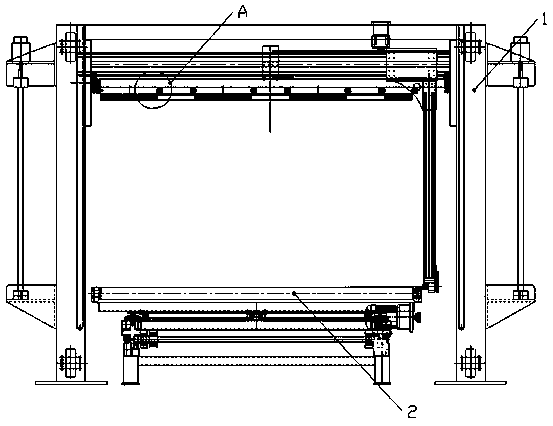
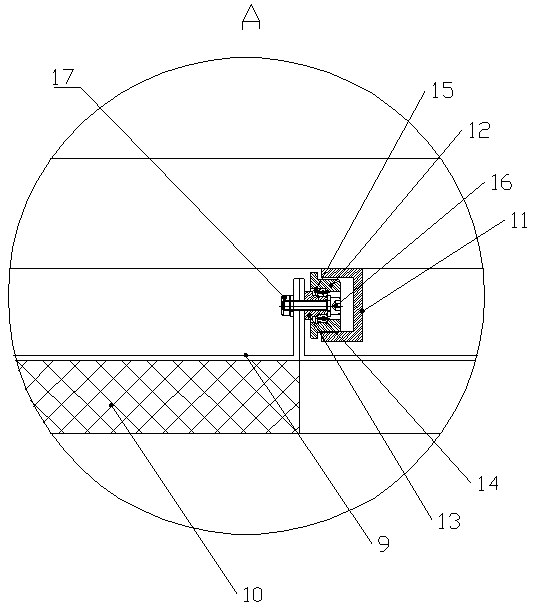
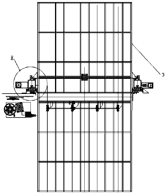
[0036] Such as Figure 1-Figure 7 A kind of horizontal ring knife numerical control cutting device shown, comprises

[0037] A delivery mechanism 2, the delivery mechanism 2 includes a delivery support 21, a work platform is installed on the delivery support 21, the work platform is composed of a rotating platform 22 and a fixed platform 23 distributed up and down, and the rotating platform 22 is provided with a conveyor belt or Conveyor roller 24.

[0038] The rotating platform 22 is driven by a rotating mechanism to rotate 360° with the center of the fixed platform 23 as the rotation point. The rotating mechanism is: a slewing bearing 25 is arranged between the rotating platform 22 and the fixed platform 23, and the outer ring of the slewing bearing 25 and the The botto...


PUM


Abstract

The invention relates to a horizontal ring cutter numerical control cutting device. The numerical control cutting device comprises a conveying mechanism, a gantry and a pressing support, wherein the conveying mechanism comprises a conveying support, and a working platform is arranged on the conveying support; the working platform is jointly composed of a rotating platform and a fixed platform which are distributed up and down, the rotating platform is driven by a rotating mechanism to rotate, and the fixed platform is driven by a horizontal moving mechanism to move; the gantry crosses the twosides in the width direction of the conveying support; and the pressing support comprises an upper pressing support, the upper pressing support is driven by a lifting mechanism to vertically ascend and descend, a plurality of pressing plates are arranged on the upper pressing support, and each pressing plate is driven by a following mechanism to move. The horizontal ring cutter numerical control cutting device has the advantages that due to the cooperation among the conveying mechanism, the gantry and the pressing support, not only can the deviation of sponge be avoided, but also the smooth rotation of the sponge can be ensured.

Description

technical field [0001] The invention relates to a sponge cutting device, in particular to a horizontal ring knife numerical control cutting device. Background technique [0002] Commonly used sponges are divided into three types according to their structure: high-density sponges, medium-density sponges, and low-density sponges. In the production process of sponge products, the produced foamed sponge is generally cut into required specifications on a cutting machine according to the needs of use. [0003] For example, in the patent CN208914238U, a sponge cutting machine with a limit device is mentioned, which includes a gantry frame, a base, and a limit mechanism. It is characterized in that the gantry frame is fixed on the base, and the limit The mechanism is fixed on both sides and the upper end of the gantry frame. The limit mechanism includes a mounting column, a fixing plate, a sleeve, an adjusting straight rod, a mounting plate, and a roller. The mounting column is fix...

Claims


Application Information

Patent Timeline
IPC IPC(8): B26D7/06B26D7/02
CPCB26D7/02B26D7/0616B26D7/0625
Inventor 王华
Owner 南通宏昇机械配件有限公司
Why Eureka
Try Eureka