Displacement vehicle

A vehicle body and frame technology, which is applied in the field of medical patient displacement vehicles, can solve the problems of increasing failure rate, complicated design structure, complicated control method, etc., and achieves the effect of smooth transmission, compact structure and simplified transmission structure.

Pending Publication Date: 2020-05-19
沛霖医疗技术(广州)有限公司
View PDF1 Cites 4 Cited by
  • Summary
  • Abstract
  • Description
  • Claims
  • Application Information

AI Technical Summary

Problems solved by technology

[0004] The way to realize the autorotation or stop autorotation of the cloth winding shaft adopts the joint cooperation of the clutch gear, the long rack, the clutch, and the clutch driving mechanism, as shown in the accompanying drawings 16-17 of this patent specification. The disadvantage is that the design structure is complicated, the control method is complicated, and it is easy to Fault occurs; if the clutch adopts the jaw clutch, that is, the mechanical control structure that engages and separates the two clutch gears through the fixed clutch gear and the movable clutch gear, when it needs to be combined, when the two teeth of the two clutch gears are not coordinated , it will cause the combination to be not smooth, and when separation is required, there will be separation resistance when the two teeth are meshed, resulting in a large difference in movement and positioning, and the transfer of the patient cannot be completed satisfactorily.
[0005] Another example is the attached patent specification Figure 11-12 , as shown in Figure 17, the clutch drive mechanism adopts multiple transmission modes such as small rack, pinion, tension rod, rocker arm, and push rod. The structure and transmission mode are complicated, and the failure rate is also increased.

Method used


Image

  • Displacement vehicle
  • Displacement vehicle
  • Displacement vehicle

Examples


Embodiment Construction

[0042] Below, the present invention will be further described in conjunction with the accompanying drawings and specific implementation methods. It should be noted that, under the premise of not conflicting, the various embodiments described below or the technical features can be combined arbitrarily to form new embodiments. .

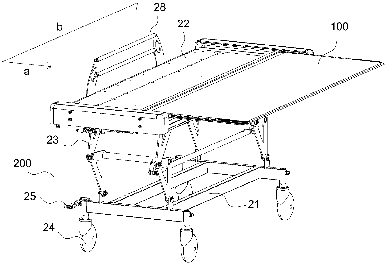
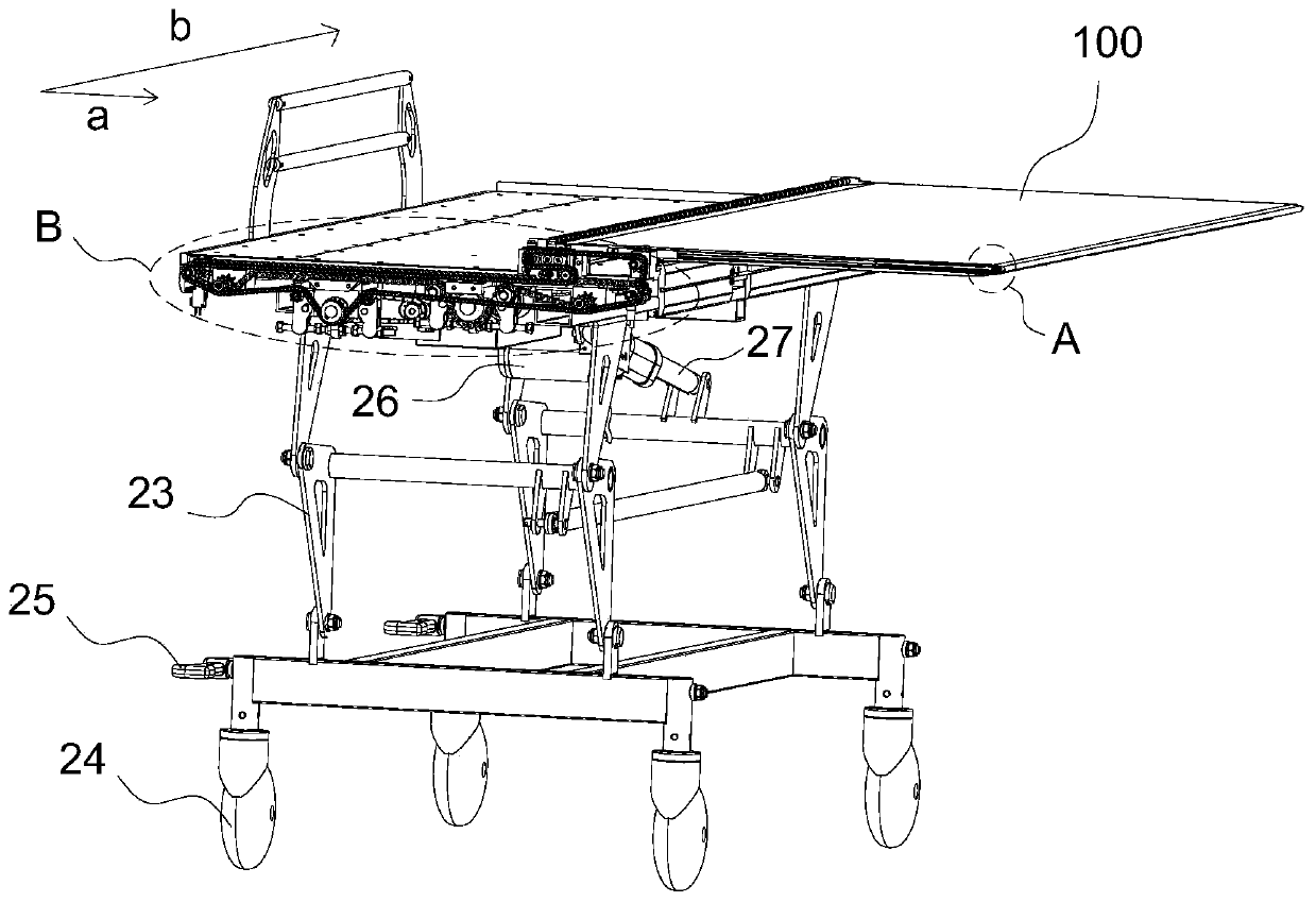
[0043] This embodiment is one of the preferred embodiments of the present invention, such as Figure 1-14 As shown, a shift car includes a car body 200 with a lifting mechanism and universal casters installed, and a mobile bed board mechanism 100 for laterally moving patients; the mobile bed board mechanism is installed on the vehicle frame 22 of the car body Above; in this embodiment, the movement direction of receiving and sending patients is realized by moving the bed board mechanism forward and backward, as in the horizontal direction, such as figure 1 The a direction shown; on the same horizontal plane, the vertical direction is the direction pe...


PUM


Abstract

The invention discloses a displacement vehicle which comprises a vehicle body and a moving bed plate mechanism, wherein the vehicle body is provided with a lifting mechanism; universal foot wheels aremounted on the vehicle body; the moving bed plate mechanism is used for receiving and transporting patients in a transversely moving manner; the moving bed plate mechanism is mounted on the frame ofthe vehicle body; the moving bed plate mechanism comprises a cloth coiling shaft frame, a cloth coiling shaft, an end connector base, an upper moving plate, lower moving cloth, a lower moving plate, lower moving cloth, a first chain wheel assembly and a ratchet wheel assembly. The displacement vehicle is characterized in that due to arrangement of the first chain wheel assembly, the ratchet wheelassembly and a first chain wheel motor, a conventional transmission mode that a clutch gear, a long rack, a clutch and a clutch driving mechanism cooperate with one another is replaced, the transmission structure of the moving bed plate mechanism is greatly simplified, the displacement vehicle is compact in structure and smooth in transmission, meanwhile, operation of the displacement vehicle is humanized, and positions of the patients can be corrected in necessary.

Description

technical field [0001] The invention relates to a transport tool technology for loading and unloading patients, in particular to a medical patient lifting vehicle suitable for transporting postoperative patients in hospitals or transporting patients who are easily injured again during the transport process. Background technique [0002] At present, the lifting cart is used to move and transfer patients with mobility problems before and after the operation, and move the patient from the hospital bed to the lifting cart, and then from the lifting cart to the operating table or equipment requiring examination / treatment, or reverse transfer. Especially for patients with wounds or patients who have undergone severe spine, cervical spine, and thoracic spine operations, the birth of the lifting car reduces the labor intensity of medical staff and avoids the possibility of bringing the patient several times during the transfer period before and after surgery. The secondary injury of...

Claims


Application Information

Patent Timeline
Patent Type & Authority Applications(China)
IPC IPC(8): A61G1/02A61G1/04
CPCA61G1/02A61G1/04A61G2203/10
Inventor 李淼邓伟民
Owner 沛霖医疗技术(广州)有限公司
Why Eureka
Try Eureka