
Variable wheel diameter mechanism

A wheel diameter and variable technology, applied in the direction of wheels, motor vehicles, tire parts, etc., can solve the problems of easy subsidence of the chassis, affecting the field operation efficiency, operation quality, and easy tire slippage, etc., to improve the chassis ground clearance, The effect of improving field passing performance and reducing wheel slip rate

Pending Publication Date: 2019-10-25
NANJING AGRI MECHANIZATION INST MIN OF AGRI
View PDF2 Cites 2 Cited by
  • Summary
  • Abstract
  • Description
  • Claims
  • Application Information

AI Technical Summary

Problems solved by technology

Due to the current centralized contiguous and standardized planting of farmland, in order to meet the needs, the ground plant protection equipment is developing in the direction of large-scale, resulting in a relatively large increase in the length of the sprayer's boom, the volume of the medicine box, and the weight of the whole machine. As a result, when the ground sprayer is working in the field, the chassis is easy to sink, the tires are easy to slip, and the slip rate increases, which affects the efficiency and quality of field work.
[0003] In view of the above problems, people have designed a boat tractor, which can solve this problem better, but because the boat tractor is easy to damage the crops when performing field management operations, it is not suitable for plant protection operations; at the same time, ZL201010117489.2 designed a A wheel with a variable diameter, but it needs to provide additional power to drive it to change its diameter, and it is used in terrain detection and other occasions; patent ZL201410432127.0 designs a deformable wheel mechanism, which increases the ground contact by rotating the tire block The area increases the driving force of the ground to the wheels, but it increases the width of the tires and increases the pressure loss of field crops during deformation operations.

Method used


Image

  • Variable wheel diameter mechanism
  • Variable wheel diameter mechanism
  • Variable wheel diameter mechanism

Examples


Embodiment Construction

[0036] The present invention will be further explained below in conjunction with the accompanying drawings and specific embodiments.

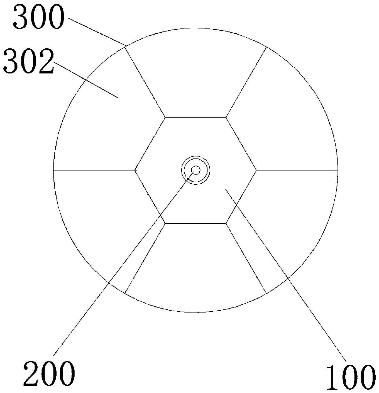
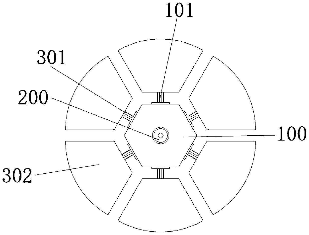
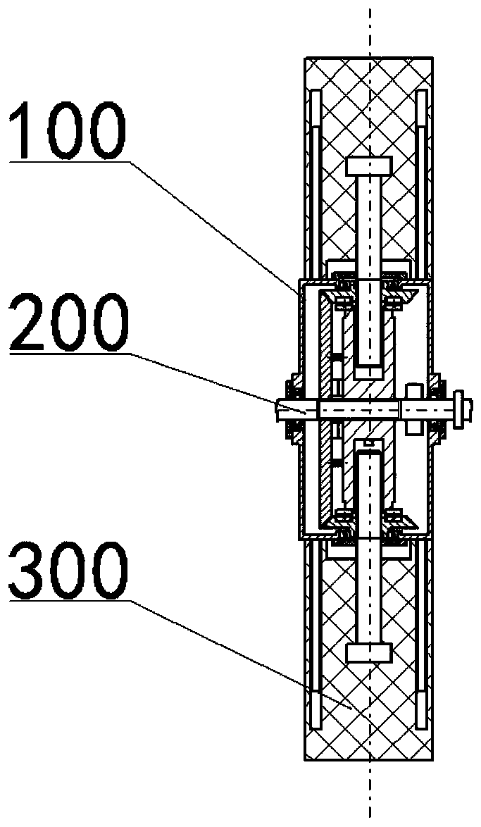
[0037] Figure 1a It is the outline drawing of the front wheel with reduced diameter. Such as Figure 1a As shown, a variable wheel diameter mechanism of the present invention includes a hub component 100 , a drive shaft 200 and a tire component 300 . The hub component 100 is connected to the driving shaft 200 through a spline, and the cross section of the hub component 100 is a regular polygonal structure. In the present invention, the hub component 100 is a regular hexagonal structure. The tire component 300 includes several tire blocks 302 equally divided, and the number of the tire blocks 302 corresponds to the number of sides of the hub component 100; the outer side of the tire block 302 is an arc structure, and the inner side is a The tire blocks 302 are respectively installed on the corresponding side surfaces of the hub component 100 o...


PUM


Abstract

The invention discloses a variable wheel diameter mechanism. The variable wheel diameter mechanism comprises a hub component (100), a driving shaft (200) and a tire component (300), wherein the hub component (100) is arranged on the driving shaft (200), the section of the hub component (100) is of a regular polygon structure, the tire component (300) comprises a plurality of tire blocks (302) which are equally divided, the number of the tire blocks (302) corresponds to the number of edges of the hub component (100), the outer sides of the tire blocks (302) are of arc structures, the inner sides of the tire blocks (302) are the mounting surfaces corresponding to the side surfaces of the hub component (100), and the tire blocks (302) are correspondingly mounted on the side surface of the corresponding side surfaces of the hub component (100) so as to form a round tire. According to the variable wheel diameter mechanism, the wheel diameter of a wheel can be changed in real time, the sliprate of the wheel is reduced, the slip of the wheel is reduced, the driving performance of a vehicle is improved, and the variable wheel diameter mechanism can adapt to various terrains and landforms.

Description

technical field [0001] The invention relates to a variable wheel diameter mechanism, specifically, a mechanism capable of changing the size of the wheel diameter in real time, so that the tire is not easy to slip and realizes stable walking. Background technique [0002] The ground plant protection sprayer has the advantages of high efficiency and convenience, and has made important contributions to the high yield and harvest of my country's grain. Due to the current centralized contiguous and standardized planting of farmland, in order to meet the needs, the ground plant protection equipment is developing in the direction of large-scale, resulting in a relatively large increase in the length of the sprayer's boom, the volume of the medicine box, and the weight of the whole machine. As a result, when the ground sprayer is working in the field, the chassis is easy to sink, the tires are easy to slip, and the slip rate increases, which affects the efficiency and quality of fie...

Claims


Application Information

Patent Timeline
IPC IPC(8): B60B19/02B60C7/08A01M7/00
CPCB60B19/02B60C7/08A01M7/0082B60B2900/551B60C2200/08
Inventor 丁素明薛新宇顾伟崔龙飞蔡晨周立新张玲金永奎秦维彩陈晨王宝坤
Owner NANJING AGRI MECHANIZATION INST MIN OF AGRI
Learn More