A deep sea equipment buoyancy adjustment system and its working method

A technology of buoyancy adjustment and working method, which is applied in the directions of fluid pressure actuation system components, mechanical equipment, transportation and packaging, etc., can solve the problems of shortening the underwater working time of deep-sea equipment, underutilizing seawater pressure, and consuming more energy.

Active Publication Date: 2021-03-26
SHANDONG UNIV
View PDF12 Cites 2 Cited by
  • Summary
  • Abstract
  • Description
  • Claims
  • Application Information

AI Technical Summary

Problems solved by technology

[0004] However, the existing buoyancy adjustment systems are generally installed on the seabed to increase the volume of the buoyancy oil bladder. At this time, the seawater pressure is relatively high, and more energy is required
When reducing the volume of the buoyant oil bladder, hydraulic pumps are generally used to pump out the hydraulic oil from the buoyant oil bladder, which does not make full use of the pressure of seawater and consumes energy
Therefore, the existing buoyancy adjustment system consumes a lot of energy, which greatly shortens the underwater working time of deep sea equipment

Method used


Image

  • A deep sea equipment buoyancy adjustment system and its working method
  • A deep sea equipment buoyancy adjustment system and its working method
  • A deep sea equipment buoyancy adjustment system and its working method

Examples


Embodiment 1

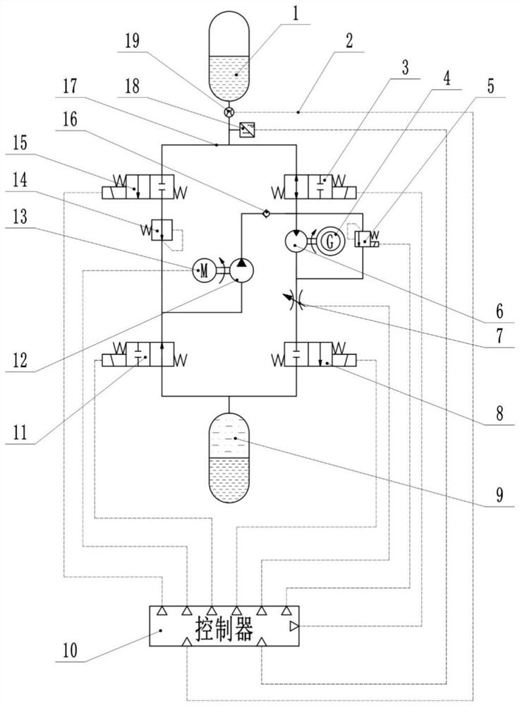
[0069] A buoyancy adjustment system for deep sea equipment, such as figure 1 As shown, it includes buoyancy oil bag 1, oil outlet normally open electromagnetic reversing valve 3, overflow valve 5, hydraulic motor 6, throttle valve 7, oil outlet normally closed electromagnetic reversing valve 8, oil storage oil Capsule 9, controller 10, oil inlet normally open electromagnetic reversing valve 11, hydraulic pump 12, pressure reducing valve 14, oil inlet normally closed electromagnetic reversing valve 15, check valve 16, pressure transmitter 18 and flow meter 19;

[0070] The oil storage bag 1 is respectively connected with the normally closed electromagnetic reversing valve 8 of the oil outlet and the normally open electromagnetic reversing valve 11 of the oil inlet, and the oil inlet of the hydraulic pump 12 is respectively connected with the normally open electromagnetic reversing valve of the oil inlet Valve 11 and pressure reducing valve 14, the oil outlet of hydraulic pump...

Embodiment 2

[0074] A buoyancy adjustment system for deep sea equipment, the structure is as shown in Example 1, the difference is that the oil storage tank 9 is a piston structure, one end is an oil storage chamber, the other end is a vacuum negative pressure chamber, and the pressure is 0.5 standard Atmospheric pressure, the volume of the buoyant oil bag 1 changes with the internal oil volume.

Embodiment 3

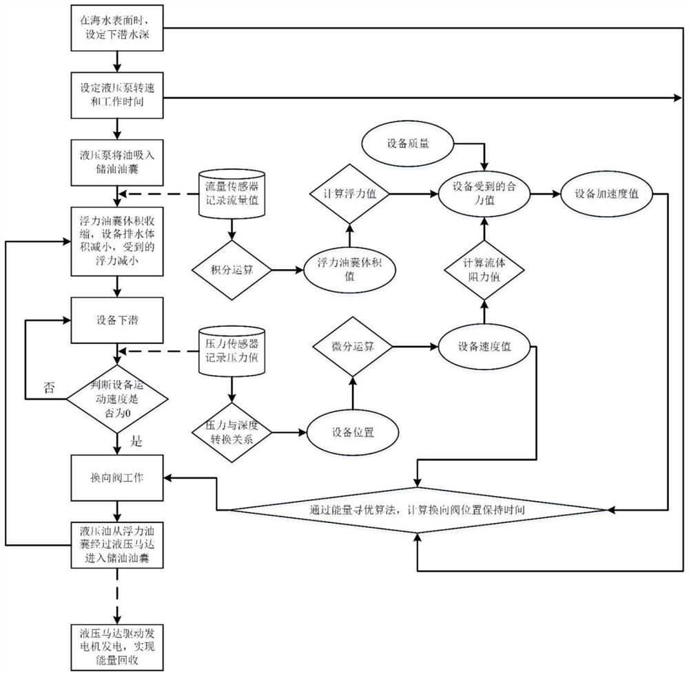
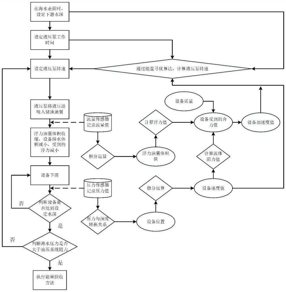
[0076] A working method of a buoyancy adjustment system for deep sea equipment. On the sea surface, when the damping of the hydraulic system is small, the controller 10 drives the normally closed electromagnetic reversing valve 8 at the oil outlet to reversing, and sends the overflow to the overflow valve 5 signal, send a throttling signal to the throttle valve 7, so that the hydraulic oil enters the oil storage bag 9 from the buoyancy oil bag 1 through the overflow valve 5 under the action of negative pressure; when the damping of the hydraulic system is large, the controller 10 Drive oil outlet normally open electromagnetic reversing valve 3, oil outlet normally closed electromagnetic reversing valve 8, oil inlet normally open electromagnetic reversing valve 11 and oil inlet normally closed electromagnetic reversing valve 15 to perform switching At the same time, it sends a speed signal to the motor 13, an overflow signal to the relief valve 5, and a throttling signal to the ...


PUM


Abstract

The invention relates to a deep sea equipment buoyancy regulating system and a working method thereof, and belongs to the field of marine exploration equipment. The system comprises a buoyancy oil bag, an oil outlet normally open type electromagnetic reversing valve, an overflow valve, a hydraulic motor, a throttling valve, an oil outlet normally closed type electromagnetic reversing valve, an oilstorage oil bag, a controller, an oil inlet normally open type electromagnetic reversing valve, a hydraulic pump, a pressure reducing valve, an oil inlet normally closed type electromagnetic reversing valve, a one-way valve, a pressure transmitter and a flow meter, wherein the controller is connected with the flow meter, the pressure transmitter, the oil outlet normally open type electromagneticreversing valve, the overflow valve, the throttling valve, the oil outlet normally closed type electromagnetic reversing valve, the oil inlet normally closed type electromagnetic reversing valve, themotor and the oil inlet normally open type electromagnetic reversing valve through signal lines. According to the system, electric energy can be emitted by utilizing the pressure of seawater, the working state of a reversing valve of a hydraulic system is controlled, the energy consumption in the working process of the deep sea equipment buoyancy regulating system is reduced, and the working timeof deep sea equipment is prolonged.

Description

technical field [0001] The invention relates to a buoyancy adjustment system for deep-sea equipment and a working method thereof, belonging to the technical field of marine detection equipment. Background technique [0002] Buoyancy adjustment technology is widely used in deep-sea mobile platforms such as underwater gliders and autonomous underwater vehicles, and is a key core technology for exploring the ocean. [0003] At present, the commonly used buoyancy adjustment technology is to use variable-volume oil bladders as buoyancy oil bladders. By changing the volume of buoyancy oil bladders, the displacement volume of deep-sea equipment will change, thereby changing the buoyancy of seawater received by deep-sea equipment. In the case of , the resultant force on the equipment changes, resulting in an upward or downward force. For example, the Chinese invention patent with application number 201711387767.4 discloses an underwater buoyancy adjustment device, which is driven b...

Claims


Application Information

Patent Timeline
Patent Type & Authority Patents(China)
IPC IPC(8): B63G8/14B63C11/52F15B13/04F15B21/02F15B21/14
CPCB63C11/52B63G8/14F15B13/04F15B21/02F15B21/14
Inventor 薛钢刘延俊郭磊杨旭司伟伟李志彤郭凤祥
Owner SHANDONG UNIV
Why Eureka
Try Eureka