Dual-fin array sonar equipment

A sonar and equipment technology, applied in the field of single-fin array sonar equipment, can solve the problems of affecting UUV fluid performance, maneuverability and speed, large work complexity, unfavorable UUV release and recovery, etc., to prolong underwater working time. , Improve the fixing strength, and facilitate the release and recovery effect

Inactive Publication Date: 2013-03-13
INST OF ACOUSTICS CHINESE ACAD OF SCI +1
View PDF0 Cites 0 Cited by
  • Summary
  • Abstract
  • Description
  • Claims
  • Application Information

AI Technical Summary

Problems solved by technology

However, these two types of sonar have obvious disadvantages, because whether it is the front nose array or the towed array, it will seriously affect the fluid performance, maneuverability and speed of the UUV. In addition, because they are all installed in a disassembled and external installation method, the work is very complicated. , which is not conducive to the release and recovery of UUV

Method used


Image

  • Dual-fin array sonar equipment
  • Dual-fin array sonar equipment
  • Dual-fin array sonar equipment

Examples


Embodiment 1

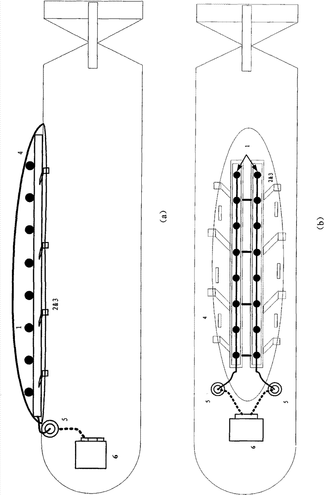
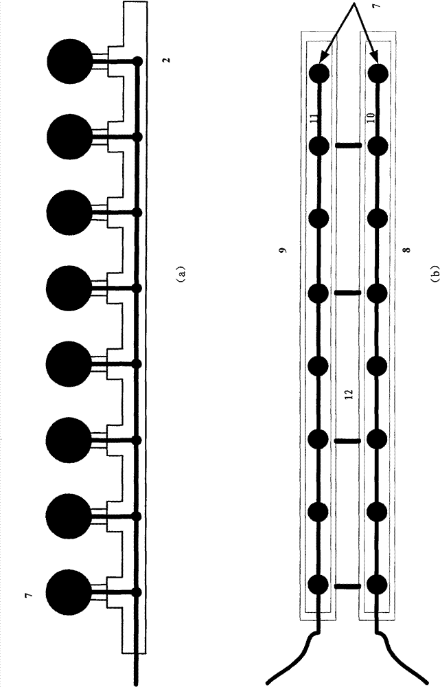
[0036] In the double dorsal fin array sonar system for the underwater unmanned vehicle of this embodiment, the main body array part is installed on the back of the underwater unmanned vehicle, and is symmetrically distributed according to the central axis. The front outlet of the array cable enters the interior of the underwater unmanned vehicle. , the whole system consists of figure 1 As shown, it includes five parts including double dorsal fin hydrophone array, double array bracket and holder, conformal shroud, watertight interface and signal processor.

[0037] At this installation position, the installation and work of the dual dorsal fin array sonar for underwater unmanned vehicles provided by this implementation includes the following steps:

[0038] 1) The double dorsal fin hydrophone arrays are respectively installed and fixed on the left and right main skeletons of the double array bracket, and the array cables are respectively drawn out through the hollow main skelet...

Embodiment 2

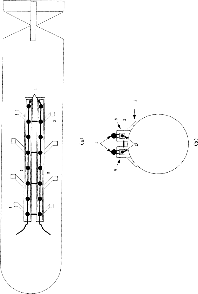
[0070] In the double dorsal fin array sonar system for the underwater unmanned vehicle of this embodiment, the main body array part is installed on the abdomen of the underwater unmanned vehicle, and is symmetrically distributed on the left and right of the central axis. , the whole system consists of Figure 9 As shown, it includes five parts including double dorsal fin hydrophone array, double array bracket and fixture, conformal shroud, watertight interface and signal processor.

[0071] At this installation position, the installation and work of the dual dorsal fin array sonar for underwater unmanned vehicles provided by this implementation includes the following steps:

[0072] 1) The double dorsal fin hydrophone arrays are respectively installed and fixed on the left and right main skeletons of the double array bracket, and the array cables are respectively drawn out through the hollow main skeleton;

[0073] 2) The main skeleton of the double-array bracket is installed...


PUM


Abstract

The invention relates to dual-fin array sonar equipment, which comprises a hydrophone array, an array bracket and a guide hood. The dual-fin array sonar equipment is characterized in that: the array bracket is fixed on the back or belly of the shell of an underwater unmanned vehicle; all array elements of the hydrophone array are fixedly arranged on the array bracket; the hydrophone array comprises two parallel single-line arrays; the two parallel single-line arrays have the array elements which are arranged in a mode of mirror symmetry along the axial line of the back or belly of the shell of the underwater unmanned vehicle; the guide hood is connected with underwater unmanned vehicle shell; and the hydrophone array and the array bracket are positioned in a cavity formed between the guide hood and the underwater unmanned vehicle shell. Through a dual-dorsal fin array, a fish bone like bracket and a conformal guide design, the dual-fin array sonar equipment improves the installation suitability of a passive detection sonar on an underwater unmanned vehicle and overcomes the problem of blurry left and right boards of the single-line arrays so as to enable the underwater unmanned vehicle to judge the left and right boards of a target without driving of an engine.

Description

technical field [0001] The invention belongs to the field of sonar equipment, in particular to a single-fin array sonar equipment used for a miniaturized underwater active platform. Background technique [0002] Miniaturized underwater activity platforms mainly include underwater unmanned vehicles and underwater towed detection platforms. Among them, the underwater unmanned vehicle (UUV, Underwater Unmanned Vehicle) has a very important position in the modern marine combat system due to its technical characteristics such as flexible maneuverability, good concealment and large endurance. UUV is known as the "force multiplier" of the navy and is widely used in modern naval warfare, especially in long-range target detection with obvious advantages such as concealment and maneuverability. However, compared with ships, UUVs are smaller in size and have limited space. How to install detection sonar on UUV has always been an urgent problem to be solved in UUV remote detection. At...

Claims


Application Information

Patent Timeline
Patent Type & Authority Patents(China)
IPC IPC(8): G01S7/521G01S15/88B63G8/39
Inventor 李宇朱沛胜黄海宁张春华
Owner INST OF ACOUSTICS CHINESE ACAD OF SCI
Why Eureka
Try Eureka