Unstacking machine

A technology of depalletizer and clamping mechanism, applied in the direction of depalletization, transportation and packaging of objects, can solve the problems of low depalletization efficiency, poor stability, etc., to improve depalletization efficiency, improve the degree of automation, and use simple methods. Effect

Pending Publication Date: 2019-10-25
HARBIN BOSHI AUTOMATION
View PDF0 Cites 5 Cited by
  • Summary
  • Abstract
  • Description
  • Claims
  • Application Information

AI Technical Summary

Problems solved by technology

[0009] The present invention solves the problems of low destacking efficiency and poor stability during the use of existing destacking equipment

Method used


Image

  • Unstacking machine
  • Unstacking machine
  • Unstacking machine

Examples


specific Embodiment approach 1

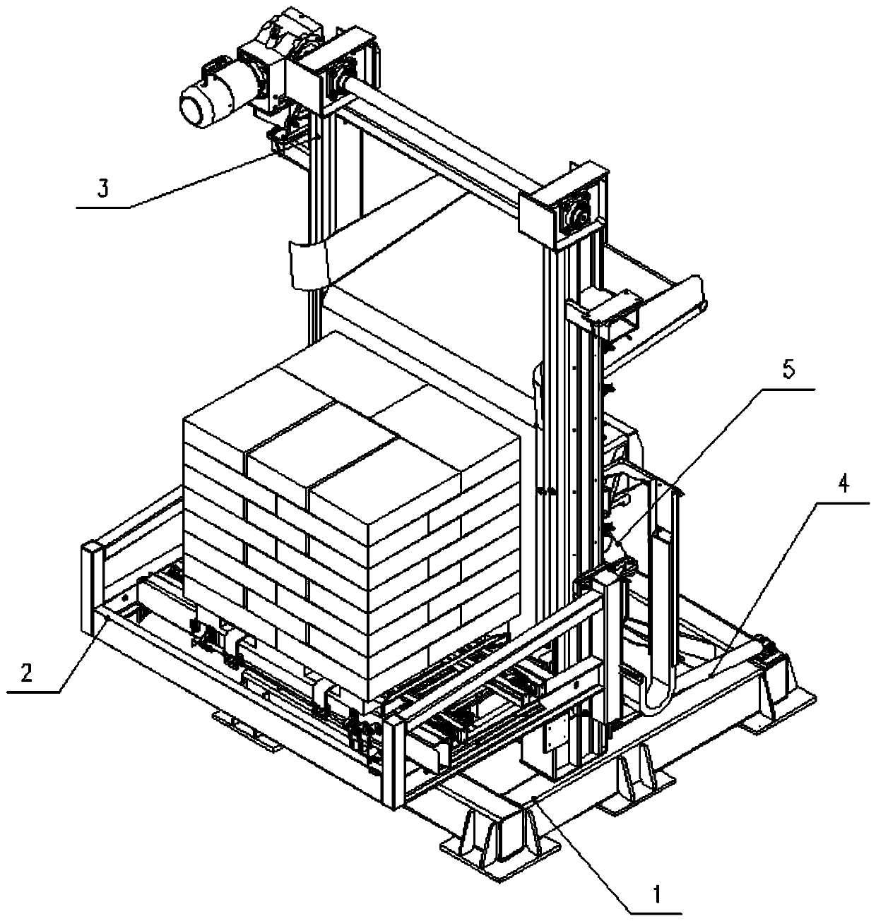
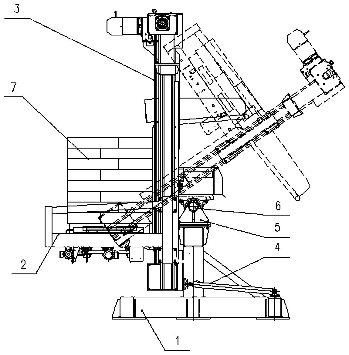
[0041] Specific implementation mode one: combine Figure 1-Figure 4 , Figure 12-Figure 14Describe this embodiment, a kind of unstacking machine of this embodiment, comprise base 1, lifting platform 2, lifting device 3, hydraulic cylinder 4 and turning shaft seat 5, turning shaft seat 5 is installed on base 1, and lifting device 3 passes through The overturning central axis 6 is hingedly mounted on the overturning shaft seat 5, the cylinder end of the hydraulic cylinder 4 is installed on the base 1, the output end of the hydraulic cylinder 4 is connected with the lifting device 3, and the lifting platform 2 is installed on the On the lifting device 3, the lifting platform 2 performs linear reciprocating motion on the lifting device 3. In such a setting, turning over the shaft seat 5 realizes the hinged state of the base 1 and the lifting device 3, and under the push of the hydraulic cylinder 4, the lifting device 3 can achieve pitching motion relative to the base 1, and the l...

specific Embodiment approach 2

[0042] Specific implementation mode two: combination figure 1 , Figure 5 Describe this embodiment, a kind of unstacking machine of this embodiment, described base 1 comprises base frame 1-1, door frame 1-2 and oil cylinder tailstock 1-3, and base frame 1-1 is square tube welded assembly The square frame that is made, the door frame 1-2 and the oil cylinder tailstock 1-3 are all fixedly installed on the base frame 1-1, and the cylinder end of the hydraulic cylinder 4 is hinged on the oil cylinder tailstock 1-3, The top of the door frame 1-2 is processed with a flange mounting seat, and the turning shaft seat 5 is installed on the top of the door frame 1-2 in a flange manner. Set up in this way, the base frame 1-1 is a square frame made of welded square tubes. In order to strengthen the structural strength of the base 1, support beams and ribs can also be added inside the square frame, wherein the door frame 1-2 can be It is installed on the base frame 1-1 by means of welding...

specific Embodiment approach 3

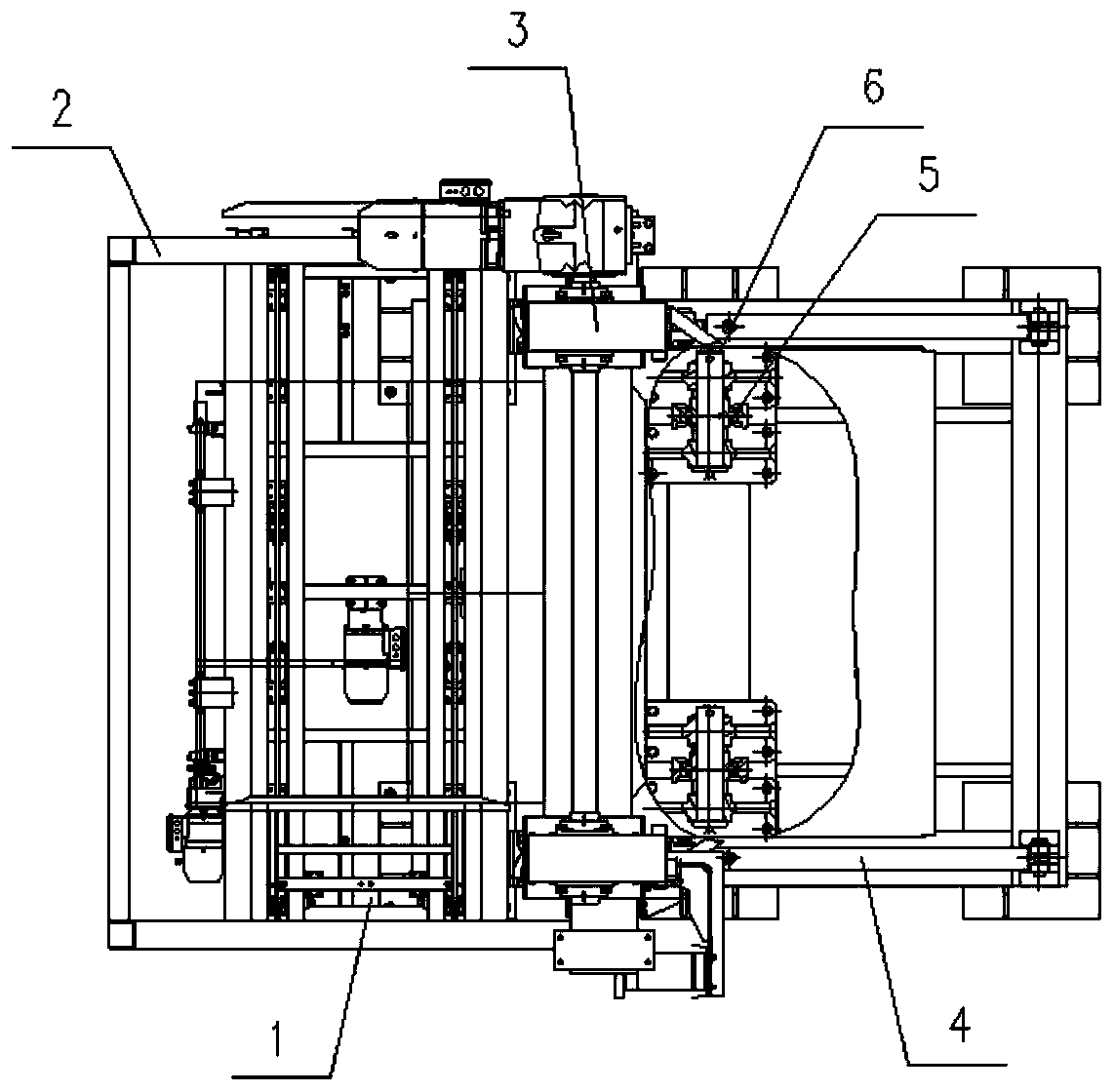
[0043] Specific implementation mode three: combination Figure 1-Figure 4 , Figure 6-Figure 9 Describe this embodiment, a depalletizer of this embodiment, the lifting platform 2 includes a material bag bracket 2-1, a pallet pushing mechanism 2-2, a clamping mechanism 2-3 and a composite rolling guide mechanism 2- 4. The material bag bracket 2-1 is a square bracket made of welded square tubes. The two ends of the material bag bracket 2-1 are equipped with a composite rolling guide mechanism 2-4, and the material bag bracket 2-1 passes through The composite rolling guide mechanism 2-4 realizes linear reciprocating sliding on the lifting device 3, the material bag bracket 2-1 is equipped with a tray pushing mechanism 2-2, and the clamping mechanism 2-3 is installed on the material bag bracket 2-1, the clamping mechanism 2-3 is on the side of the tray pushing mechanism 2-2. In this way, the lifting platform 2 includes a pallet push-out mechanism 2-2 for pushing out the pallet 8...


PUM


Abstract

The invention provides an unstacking machine, and belongs to the technical field of unstacking devices. The unstacking machine aims at solving the problems that in the use process of an existing unstacking device, the unstacking efficiency is low and stability is poor. The unstacking machine comprises a base, a lifting platform, lifting devices, hydraulic cylinders and turnover shaft bases. The turnover shaft bases are installed on the base. Each lifting device is installed on the corresponding turnover shaft base in a hinged manner through a turnover center shaft. The cylinder body ends of the hydraulic cylinders are installed on the base. The output ends of the hydraulic cylinders are connected with the lifting devices. Under the push effect of the hydraulic cylinders, the lifting devices do the pitching action relative to the base. The lifting platform is installed on the lifting devices and linearly reciprocates on the lifting devices. The automatic operation of the unstacking workcan be conveniently completed, and the unstacking efficiency is improved.

Description

technical field [0001] The invention relates to a destacking mechanism for bagged goods, belonging to the technical field of destacking equipment. Background technique [0002] Bagged goods are basically automated in terms of packaging and palletizing, but in the process of logistics transshipment, it is often necessary to dismantle the palletized bagged goods into single bags, and use bags as units for transshipment, such as loading and delivery, production Ingredients etc. in the process. [0003] At present, the automatic destacking method adopts the hand grasping method of the robot (joint type or rectangular coordinate type) with a vacuum suction cup. The disadvantages of this destacking method are as follows: [0004] 1. This method needs supporting systems such as visual recognition of stacking type, grasping (or suction) and placement operation, and the cost is relatively high; [0005] 2. Affected by the quality of materials and bags, there are low unstacking effi...

Claims


Application Information

Patent Timeline
Patent Type & Authority Applications(China)
IPC IPC(8): B65G59/08
CPCB65G59/08
Inventor 宋立志王雪松陈辉
Owner HARBIN BOSHI AUTOMATION
Why Eureka
Try Eureka