
Suspension bridge cable clamp screw axial force synchronous construction system and use method thereof

A technology of synchronous construction and screw shaft, which is applied in the direction of bridges, bridge parts, bridge construction, etc., can solve the problems of easy delay in construction period, untimely inspection of screw axial force, and large workload, so as to save construction cost and construction time, Avoid complex pull work problems and ensure the effect of construction quality

Active Publication Date: 2019-10-25
CHINA RAILWAY BRIDGE SCI RES INST LTD +1
View PDF7 Cites 6 Cited by
  • Summary
  • Abstract
  • Description
  • Claims
  • Application Information

AI Technical Summary

Problems solved by technology

[0004] However, in the current jack tensioning process, due to the different roughness of the contact surface between the nut, the spacer and the cable clamp, and the slight difference in the processing of the screw thread itself, the degree of the worker's tightening of the nut is random. Larger, the axial force loss of the screw after the jack returns oil is greater, and the randomness is also greater. According to the actual measurement of a certain bridge, the axial force loss of the screw after tensioning ranges from 10% to 60%. It is difficult to accurately control the axial force fastening construction. After the construction is completed, the axial force of the screw cannot be checked in time. Re-tensioning after the later inspection will bring a large workload, increase the construction cost and easily delay the construction period.

Method used


Image

  • Suspension bridge cable clamp screw axial force synchronous construction system and use method thereof
  • Suspension bridge cable clamp screw axial force synchronous construction system and use method thereof
  • Suspension bridge cable clamp screw axial force synchronous construction system and use method thereof

Examples


Embodiment Construction

[0038] The present invention will be further described in detail below in conjunction with the accompanying drawings and specific embodiments.

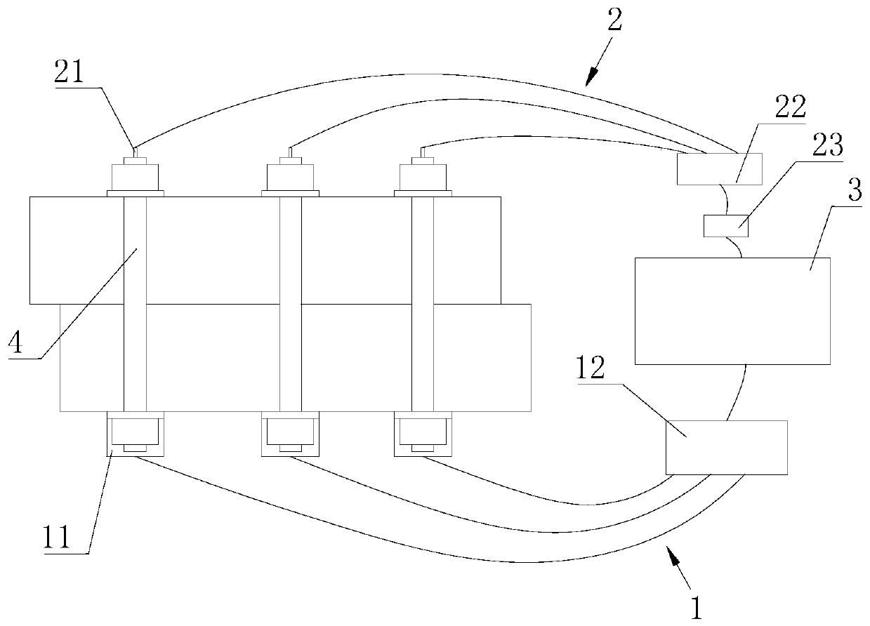
[0039] see figure 1 As shown, the embodiment of the present invention provides a suspension bridge cable clamp screw axial force synchronous construction system, including: a tensioning device 1 , an ultrasonic testing device 2 , and a control device 3 .

[0040] The stretching device 1 is used to be connected with the screw rod 4 to be stretched and to implement tension to the screw rod 4 to be stretched; the ultrasonic detection device 2 is used to be connected to the screw rod 4 to be stretched, and Ultrasonic signals are emitted in the tension screw 4, and the propagation time of the ultrasonic signal is detected to go back and forth in the tension screw 4; the control device 3 is connected to the tension device 1 and the ultrasonic detection device 2, and it is used to control the tension The pulling device 1 uses a preset axial...


PUM


Abstract

The invention discloses a suspension bridge cable clamp screw axial force synchronous construction system and a use method thereof, and relates to the technical field of bridge engineering construction. The system comprises a tensioning device, an ultrasonic detection device and a control device, wherein the tensioning device is used for being connected with a to-be-tensioned screw and tensioningthe to-be-tensioned screw; the ultrasonic detection device is used for being connected with the to-be-tensioned screw, transmitting an ultrasonic signal to the to-be-tensioned screw, and detecting the transmission time of round trip of the ultrasonic signal in the to-be-tensioned screw; and the control device is connected with the tensioning device and the ultrasonic detection device and is usedfor calculating correction construction axial force F2 in the to-be-tensioned screw according to t2, t3 and a preset formula, and the tensioning device is controlled to carry out tensioning on the to-be-tensioned screw rod by adopting the correction construction axial forceF2. According to the system, a correction scheme is formulated for the retraction loss condition of single screw tensioning,and the engineering problems of large axial force loss and large randomness of the screw after a nut is screwed are well solved.

Description

technical field [0001] The invention relates to the technical field of bridge engineering construction, in particular to a suspension bridge cable clamp screw axial force synchronous construction system and a use method thereof. Background technique [0002] The cable clamp of the suspension bridge is one of the main components of the superstructure of the suspension bridge. The main defect in the use process is that the cable clamp slips on the main cable. Article 9 requires inspection of "whether the upper end of the suspender rod of the suspension bridge and the cable clip of the main cable are loose, displaced and damaged". Article 7.2.1 of the Technical Condition Evaluation Standard for Highway Bridges (2011) also regards the slippage of the cable clip greater than 10mm as serious defect. [0003] At present, during the actual construction of the cable clamp screw, the jack is generally used to stretch the screw to the construction axial load, and then the worker uses ...

Claims


Application Information

Patent Timeline
Patent Type & Authority Applications(China)
IPC IPC(8): E01D21/00E01D19/16G01L5/00
CPCE01D19/16E01D21/00G01L5/00
Inventor 伊建军汪正兴荆国强王波彭旭民侍刚王翔汪泽洋王梓宇马长飞刘鹏飞吴肖波
Owner CHINA RAILWAY BRIDGE SCI RES INST LTD
Learn More