Air intake system of power system and engineering machinery

A power system and air intake system technology, applied in the direction of charging system, mechanical equipment, engine components, etc., can solve the problems of increased air intake resistance of the engine, black smoke from the engine, blockage, etc.

Pending Publication Date: 2019-10-25
SANY HEAVY MACHINERY
View PDF0 Cites 1 Cited by
  • Summary
  • Abstract
  • Description
  • Claims
  • Application Information

AI Technical Summary

Problems solved by technology

[0003] figure 1 For the structural representation of the rain cap air intake system in the prior art, please refer to figure 1 , the air intake system of existing engineering machinery generally installs a rainproof cap 2' above the air filter 1' to improve the air intake system's filtration of air. The air intake system using the rainproof cap generally has the following disadvantages: the rainproof cap is generally The s

Method used


Image

  • Air intake system of power system and engineering machinery
  • Air intake system of power system and engineering machinery
  • Air intake system of power system and engineering machinery

Examples


Embodiment 1

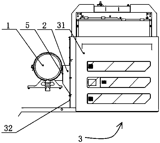
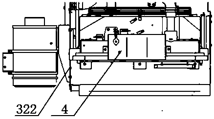
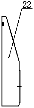
[0052] figure 2 It is a structural schematic diagram of the air intake system of the power system provided by this embodiment from a perspective, image 3 It is a schematic diagram of the internal partial structure of the air intake system of the power system provided in this embodiment, Figure 4 A structural schematic view of the air deflector and the heat dissipation engine room in the air intake system of the power system provided by this embodiment, Figure 5 for Figure 4 side view, Figure 6 A schematic structural view of the side panel in the air intake system of the power system provided by this embodiment at a viewing angle, Figure 7 The structure diagram of the cabin partition in the air intake system of the power system provided in this embodiment at one angle; please refer to Figure 2-7 , the present embodiment provides an air intake system of a power system, the air intake system of the power system of this embodiment includes an air filter 1, a shroud 2 a...

Embodiment 2

[0066] This embodiment provides a construction machine, which includes the intake system of the power system described in the first embodiment. The construction machine in this embodiment may be a rotary drilling rig.

[0067] The air intake system of the above-mentioned power system includes an air filter, a shroud and a cooling engine room;

[0068] One end of the air filter is connected to the engine intake pipe, the other end of the air filter is connected to one end of the wind deflector, and the other end of the wind deflector is connected to the heat dissipation cabin, and the heat dissipation engine compartment includes a heat dissipation The cabin body, the first cabin partition arranged in the heat dissipation cabin body, and the second cabin partition arranged on the outer surface of the heat dissipation cabin body, the first cabin partition is provided with a first air inlet, A second air inlet connected to the wind deflector is opened on the second cabin partitio...


PUM


Abstract

The invention discloses an air intake system of a power system and engineering machinery. The air intake system of the power system comprises an air filter, a flow guide cover and a radiating cabin, wherein one end of the air filter is connected with an engine air intake pipe, the other end of the air filter is connected with the flow guide cover, and the other end of the flow guide cover is connected with the radiating cabin; the radiating cabin comprises a radiating cabin body, a first cabin partition arranged in the radiating cabin body and a second cabin partition arranged on the outer surface of the radiating cabin body, first air inlets are formed in the first cabin partition, a second air inlet connected with the flow guide cover is formed in the second cabin partition, and the airinlet area of the first air inlets can be adjusted. The air intake system of the power system has the advantages that the problems that the air intake pipe is sucked flat or an engine emits black smoke because the second air inlet is blocked by large impurities and large particles are solved, standard design of a rainproof cap is avoided, and the problem of limited air intake amount of air inletsof existing rainproof caps is solved.

Description

technical field [0001] The invention belongs to the technical field of engineering machinery, and in particular relates to an intake system of a power system and an engineering machinery. Background technique [0002] The performance of construction machinery mainly depends on the performance of the engine, and the performance of the engine is often related to the quality of the intake air. [0003] figure 1 For the structural representation of the rain cap air intake system in the prior art, please refer to figure 1 , the air intake system of existing engineering machinery generally installs a rainproof cap 2' above the air filter 1' to improve the air intake system's filtration of air. The air intake system using the rainproof cap generally has the following disadvantages: the rainproof cap is generally The standard design parts matched with the air filter, the air intake of the rainproof cap is limited, and the rainproof cap is exposed outside, which is often blocked by...

Claims


Application Information

Patent Timeline
IPC IPC(8): F02M35/04F02M35/024F02M35/10
CPCF02M35/024F02M35/02466F02M35/044F02M35/10262F02M35/10268
Inventor 陈素梅赵伟泉姚炜
Owner SANY HEAVY MACHINERY
Why Eureka
Try Eureka