Aluminum silicon tempered glass low-temperature fatigue detecting device
A tempered glass and fatigue detection technology, which is applied in the direction of measuring devices, testing material strength by applying repetitive force/pulsation force, testing material strength by applying stable tension/pressure, etc., can solve cumbersome operation, inconvenient operation, and very small screen requirements High-level problems, to achieve rapid negative pressure and air intake, clamping and fixing stability, good uniformity of pumping
- Summary
- Abstract
- Description
- Claims
- Application Information
AI Technical Summary
Problems solved by technology
Method used
Image
Examples
Embodiment 1
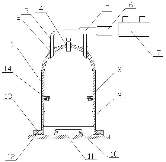
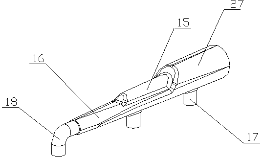
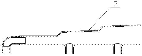
[0023] The low-temperature fatigue detection device for aluminum-silicon tempered glass of the present invention is realized in the following way: the low-temperature fatigue detection device for aluminum-silicon tempered glass of the present invention consists of a main body cover (1), an exhaust pipe (2), a connecting pipe (3), and a sealing gasket (4), air pipe assembly (5), variable diameter connector (6), three-way valve (7), annular card slot (8), compression sleeve (9), refrigerant retaining ring (10), base ( 11), sealing ring (12), sealing pressure plate (13), limit ring (14), rotating rod (21), support ring (22) and rubber pressure ring (23), the refrigerant retaining ring (10) is placed In the middle of the base (11), the inner diameter of the refrigerant retaining ring (10) gradually increases from bottom to top, the main body cover (1) is placed outside the refrigerant retaining ring (10), and the bottom of the main body cover (1) is equipped with The sealing press...
Embodiment 2
[0026] The difference between this embodiment and Embodiment 1 is: the upper side of the sealing ring (12) is provided with a plurality of inner strips (19), and the inner strips (19) are annular structures, and the plurality of inner strips ( 19) Concentric, the inner molding strip (19) is embedded on the sealing pressure plate (13), the lower side of the sealing ring (12) is provided with a plurality of sealing retaining rings (20), and the sealing baffle is ring-shaped structure, and a plurality of sealing retaining rings (20) are concentric, and the side of the sealing retaining ring (20) is arc-shaped, and the inner arc-shaped concave surface faces outward; when in use, the inner strip (19) can strengthen and seal the pressure plate (13), the sealing retaining ring (20) can better seal the base (11) and the sealing pressure plate (13), so that the main body cover (1) is in the sealing ring (12);
Embodiment 3
[0028] The difference between this embodiment and Embodiment 1 is: a guide sleeve (25) is sleeved on one end of the air extraction pipe (2), and a spherical sealing cover is installed at one end of the guide sleeve (25), and the air extraction pipe (2) There is a connecting ring (24) on the outer wall; when in use, the spherical sealing cover and the inner wall of the main cover (1) can be further sealed between the exhaust pipe (2) and the inner wall of the main cover (1) to avoid air leakage impact detection;
[0029] The inner diameter of the refrigerant retaining ring (10) is designed to gradually increase from bottom to top, so that the mouth of the refrigerant retaining ring (10) is larger, which facilitates the insertion of refrigerant, and further increases its internal space, allowing more refrigerant to be placed;
[0030] The width of the annular clamping groove (8) is designed to gradually decrease from the outside to the inside, and the rubber pressure ring (23) i...
PUM
 Abstract
Description
Claims
Application Information
 - R&D
- Intellectual Property
- Life Sciences
- Materials
- Tech Scout
- Unparalleled Data Quality
- Higher Quality Content
- 60% Fewer Hallucinations
Browse by: Latest US Patents, China's latest patents, Technical Efficacy Thesaurus, Application Domain, Technology Topic, Popular Technical Reports.
© 2025 PatSnap. All rights reserved.Legal|Privacy policy|Modern Slavery Act Transparency Statement|Sitemap|About US| Contact US: help@patsnap.com


