Supercharge Your Innovation With Domain-Expert AI Agents!

Reflective end wavelength division multiplexer

A wavelength division multiplexer and reflection end technology, applied in the field of reflection end wavelength division multiplexers, can solve the problems of low production efficiency, narrow space, difficult adjustment, etc., and achieve the effects of simple structure, improved assembly rate, and simplified structure setting.

Pending Publication Date: 2019-10-25
A-ONE TECH LTD
View PDF0 Cites 0 Cited by
  • Summary
  • Abstract
  • Description
  • Claims
  • Application Information

AI Technical Summary

Problems solved by technology

When the existing wavelength division multiplexer is manufactured, it is necessary to assemble the pigtail and adjust the angle and spacing of the fiber pigtail 1, the lens 2 and the filter 3. Since all devices need to be installed in the casing 4, the space is narrow, and the adjustment It is more difficult to make the production of the wavelength division multiplexer more complicated and the production efficiency is lower

Method used


Image

  • Reflective end wavelength division multiplexer
  • Reflective end wavelength division multiplexer
  • Reflective end wavelength division multiplexer

Examples


Embodiment Construction

[0020] The first embodiment of the reflection end wavelength division multiplexer:

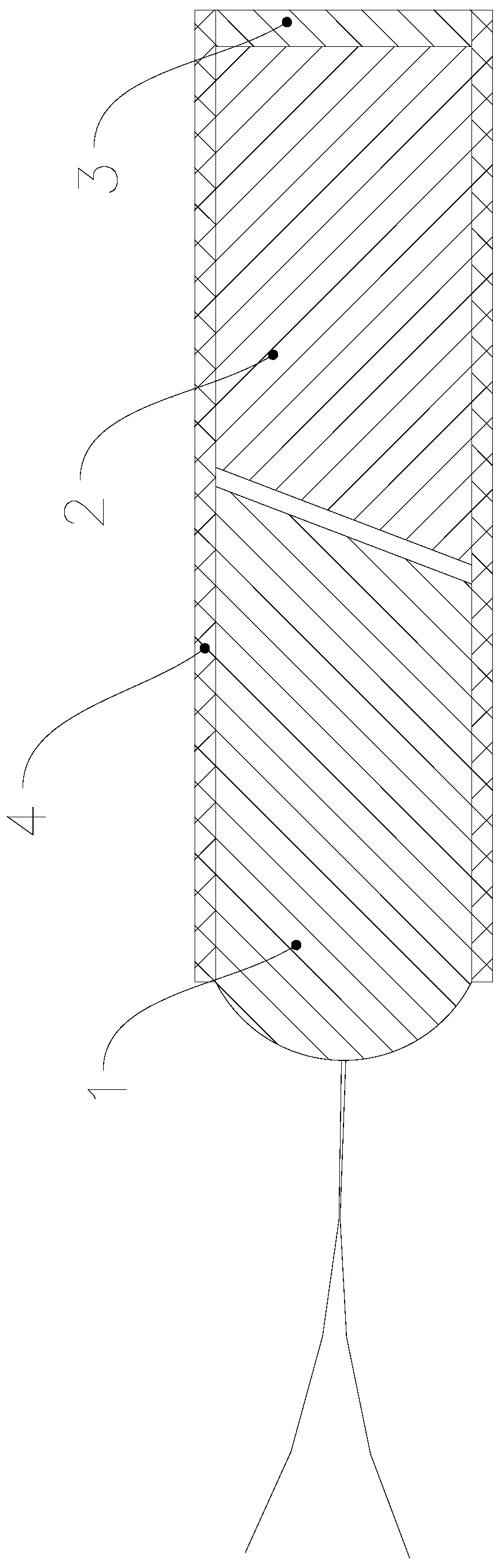
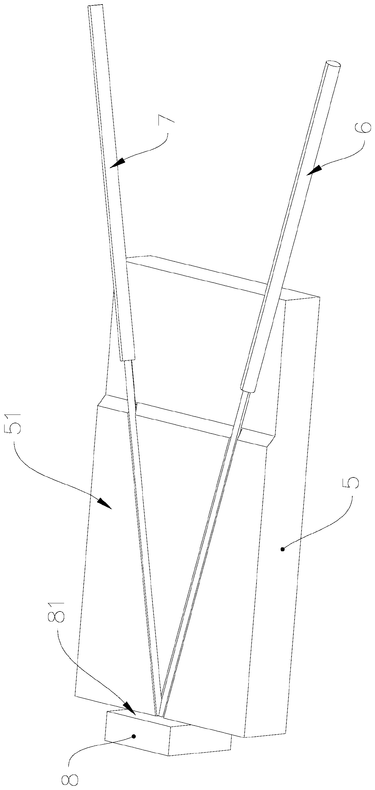
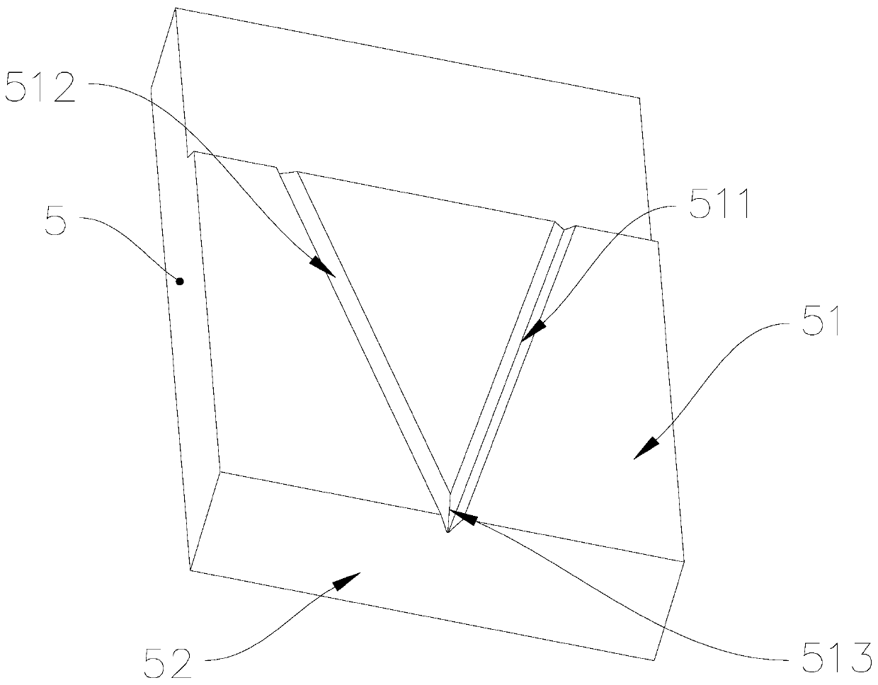
[0021] Such as figure 2 As shown, in this embodiment, the reflection end wavelength division multiplexer includes a substrate 5, an incident fiber 6, a reflection fiber 7, and a filter 8. Among them, the substrate 5 is a glass substrate. See image 3 The first side wall 51 of the substrate 5 is provided with an incident groove 511 and a reflection groove 512, and the incident groove 511 and the reflection groove 512 are intersected at a predetermined angle, preferably, the predetermined angle is 60 degrees. The filter 8 is installed at the junction 513 of the incident groove 511 and the reflection groove 512, and the filter 8 is adhered to the second side wall 52 of the substrate 5, and the second side wall 52 is perpendicular to the first side wall 51. See Figure 4 The incident optical fiber 6 is installed in the incident groove 511, the reflecting optical fiber 7 is installed in the reflecti...


PUM


Abstract

The invention provides a reflective end wavelength division multiplexer, which comprises a substrate, an incident optical fiber, a reflective optical fiber and a filter, wherein an incident groove anda reflective groove are formed in the first side wall of the substrate, the incident groove and the reflective groove intersect at a predetermined angle, the filter is mounted at a joint of the incident groove and the reflective groove, the incident optical fiber is mounted in the incident groove, the reflective optical fiber is mounted in the reflective groove, the incident end surface of the incident optical fiber at the joint is parallel to the first plane of the filter facing the joint, and the reflective end surface of the reflective optical fiber at the joint is parallel to the first plane. The reflective end wavelength division multiplexer is simple in structure and convenient in assembly.

Description

Technical field [0001] The invention relates to the technical field of wavelength division multiplexers, in particular to a reflection end wavelength division multiplexer. Background technique [0002] In an optical communication system, a wavelength division multiplexer (Wavelength Division Multipleplexer, WDM) is used to composite or decompose optical signals of different wavelengths. With the development of optical communication technology, the application of the wavelength division multiplexer becomes more and more extensive. Such as figure 1 As shown, the existing wavelength division multiplexer usually includes dual-fiber pigtail 1, lens 2, filter 3, and sleeve 4. The dual-fiber pigtail 1, lens 2, and filter 3 are installed in the sleeve in a predetermined arrangement relationship. Within 4. When manufacturing the existing wavelength division multiplexer, it is necessary to assemble pigtails and adjust the angle and spacing of the fiber pigtail 1, lens 2 and filter 3. Sinc...

Claims


Application Information

Patent Timeline
Patent Type & Authority Applications(China)
IPC IPC(8): G02B6/293G02B6/36
CPCG02B6/2938G02B6/3628
Inventor 朴木孝旭史向东黄永兴汤远亮唐梦真
Owner A-ONE TECH LTD
Features
  • R&D
  • Intellectual Property
  • Life Sciences
  • Materials
  • Tech Scout
  • Unparalleled Data Quality
  • Higher Quality Content
  • 60% Fewer Hallucinations
Learn More