Check patentability & draft patents in minutes with Patsnap Eureka AI!

A simplified multi-stage differential operational amplifier output common-mode voltage stabilization circuit

A common-mode voltage and stabilizing circuit technology, applied in the field of multi-stage differential op amp output common-mode voltage stabilizing circuits, can solve problems such as difficult common-mode voltage regulation and loop instability

Active Publication Date: 2020-12-15
杭州恒芯微电子科技有限公司
View PDF8 Cites 0 Cited by
  • Summary
  • Abstract
  • Description
  • Claims
  • Application Information

AI Technical Summary

Problems solved by technology

[0004] A typical two-stage differential op amp structure is as figure 1 As shown, under such a two-stage differential operational amplifier structure, it is necessary to achieve common-mode voltage regulation to stabilize the voltage. It is necessary to add a circuit branch and a common-mode capacitor feedback structure / independent common-mode amplifier structure, and many components need to be added to achieve , there may still be loop instability problems after the addition, and additional compensation is required, making it difficult to achieve effective and streamlined common-mode voltage regulation

Method used


Image

  • A simplified multi-stage differential operational amplifier output common-mode voltage stabilization circuit
  • A simplified multi-stage differential operational amplifier output common-mode voltage stabilization circuit
  • A simplified multi-stage differential operational amplifier output common-mode voltage stabilization circuit

Examples


Embodiment 1

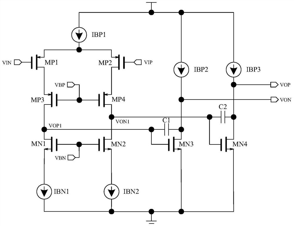
[0043] In the case of the structure where the input MOS type is PMOS, the circuit structure is as follows Figure 4 shown.

[0044] Such as Figure 4 As shown, voltage stabilizing resistor R1, voltage stabilizing resistor R2, voltage stabilizing P-type field effect transistors MP5-MP7, voltage stabilizing P-type current source IBP4 / IBP5, and voltage stabilizing N-type current source IBN3 are also added.

[0045] The drains of the voltage-stabilizing P-type field effect transistor MP5 and the voltage-stabilizing P-type field effect transistor MP6 are respectively connected to the sources of the first-stage amplifying N-type field-effect transistor MN1 and the first-stage amplifying N-type field effect transistor MN2, and the voltage stabilizing The gates of P-type FETs MP5-MP7 and the drain of the regulated P-type FET MP7 are connected to the input terminal of the regulated N-type current source IBN3, and the output terminal of the regulated N-type current source IBN3 is conne...

Embodiment 2

[0059] Figure 4 It is a structure whose input MOS type is PMOS. If the input MOS is a structure of NMOS, the mirror structure of the circuit will be as follows Figure 6 shown. Similarly, if the current capability of VCMO is relatively strong, IBN5 can be removed.

Embodiment 3

[0061] For an op amp structure with more than three levels (assumed to be N levels), the same design circuit can be applied to meet the output common-mode stabilization function of multi-level op amps, and compared with the N-level common-mode stabilization circuit of the traditional structure, in terms of area and The advantage in power consumption is greater.

[0062] For example, for a three-stage operational amplifier, the circuit structure after adopting the circuit of the present invention is as follows Figure 7 As shown, a third-stage operational amplifier circuit is also added, specifically: the gates of the third-stage amplifying N-type field effect transistor MN5 and the third-stage amplifying N-type field effect transistor MN6 are connected to the second-stage amplifying N-type field effect transistor MN6 respectively. Effect transistor MN3, the drain of the second-stage amplifying N-type field effect transistor MN4, the third-stage amplifying N-type field effect t...


PUM


Abstract

The invention discloses a streamlined multi-stage differential operational amplifier output common-mode voltage stabilization circuit. The streamlined multi-stage differential operational amplifier output common-mode voltage stabilization circuit is additionally provided with two voltage stabilization resistors, three voltage stabilization P-type field-effect tubes, two voltage stabilization P-type current sources, and a voltage stabilization N-type current source, wherein two of the voltage stabilization P-type field-effect tubes are connected to sources of two first-stage amplification N-type field-effect tubes, gates and drains of the three voltage stabilization P-type field-effect tubes are all connected to an input end of the voltage stabilization N-type current source, sources of twoof the voltage stabilization P-type field-effect tubes are serially connected and then connected to drains of two second-stage amplification N-type field-effect tubes by means of the two voltage stabilization resistors, sources of two of the voltage stabilization P-type field-effect tubes are serially connected and then connected to output ends of the voltage stabilization P-type current sources,and the sources of the voltage stabilization P-type field-effect tubes are connected to output ends of the voltage stabilization P-type current sources. The streamlined multi-stage differential operational amplifier output common-mode voltage stabilization circuit makes fine use of amplifier devices of various stages on a main amplifier signal path, can realize the stability of multi-stage differential operational amplifier output common-mode voltage by just additionally arranging a few simple circuit elements, and enhance the stability.

Description

technical field [0001] The invention relates to a voltage stabilizing circuit for operational amplifiers, in particular to a simplified multi-stage differential operational amplifier output common-mode voltage stabilizing circuit. Background technique [0002] As the basic and core component unit in the analog circuit, the operational amplifier (op amp) plays an irreplaceable role. Performance parameters such as gain, bandwidth, power consumption, and loop stability of the op amp often determine the function of the op amp. performance of the circuit. [0003] The operational amplifier with differential structure is one of the important ones. The differential operational amplifier has two input signals, positive and negative, and two output signals, positive and negative. The signal path between the two input and output signals is a fully symmetrical structure, so the differential operational amplifier It has natural advantages in common-mode rejection capability of input si...

Claims


Application Information

Patent Timeline
Patent Type & Authority Patents(China)
IPC IPC(8): G05F1/56
CPCG05F1/561
Inventor 肖马金
Owner 杭州恒芯微电子科技有限公司
Features
  • R&D
  • Intellectual Property
  • Life Sciences
  • Materials
  • Tech Scout
  • Unparalleled Data Quality
  • Higher Quality Content
  • 60% Fewer Hallucinations
Learn More