
Industrial equipment remaining useful life prediction method and system and electronic equipment

A technology of effective life and industrial equipment, applied in forecasting, electrical digital data processing, instruments, etc., can solve the problems of random aging mechanism, difficult to analyze model, difficult to establish model environmental noise and degradation mechanism, etc., to achieve good generalization ability, the effect of improving forecast speed and forecast accuracy

Active Publication Date: 2019-10-25
SHENZHEN INST OF ADVANCED TECH CHINESE ACAD OF SCI
View PDF5 Cites 17 Cited by
  • Summary
  • Abstract
  • Description
  • Claims
  • Application Information

AI Technical Summary

Problems solved by technology

Although this type of method can provide relatively accurate results, the real equipment system is usually nonlinear, and the aging mechanism of the equipment is usually random and difficult to obtain in the form of an analysis model. In actual working conditions, it is difficult to establish a Models can accommodate complex environmental noise and degradation mechanisms
[0008] 2. In the existing data-driven methods, support vector machine (SVM) modeling is used to predict the remaining effective service life of industrial equipment, but for large-scale training data and multi-classification problems, SVM consumes a lot of running memory and computing time, resulting in less accurate and slower predictions
In addition, convolutional neural network (CNN) modeling analysis is also used to predict the remaining effective life, but the original vibration signal data collected from industrial equipment is essentially a time-series operating state data, convolutional neural network (CNN) ) cannot solve the time series prediction very well, resulting in low prediction accuracy. On the other hand, if the original signal is directly applied to the convolutional neural network (CNN), the model is difficult to converge and the prediction speed is slow

Method used


Image

  • Industrial equipment remaining useful life prediction method and system and electronic equipment
  • Industrial equipment remaining useful life prediction method and system and electronic equipment
  • Industrial equipment remaining useful life prediction method and system and electronic equipment

Examples


Embodiment Construction

[0057] In order to make the purpose, technical solutions, and advantages of this application clearer, the following further describes this application in detail with reference to the accompanying drawings and embodiments. It should be understood that the specific embodiments described herein are only used to explain the application, and not used to limit the application.

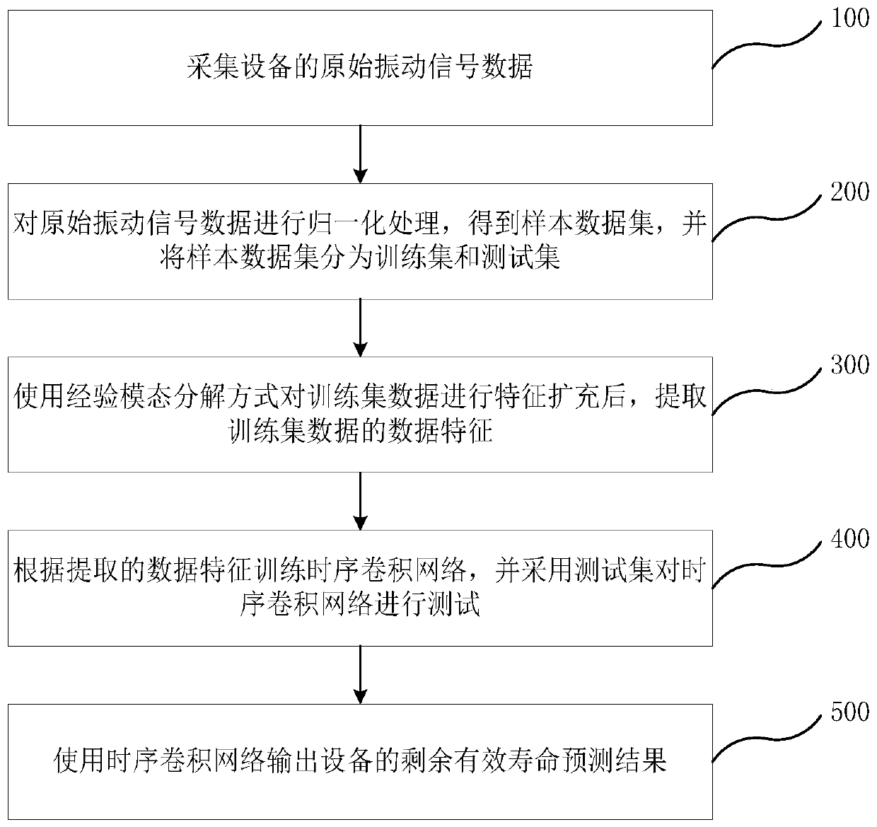
[0058] See figure 1 , Is a flowchart of the method for predicting the remaining useful life of industrial equipment in an embodiment of the present application. The method for predicting the remaining effective life of industrial equipment in the embodiment of the application includes the following steps:

[0059] Step 100: Collect raw vibration signal data of the equipment;

[0060] Step 200: normalize the original vibration signal data to obtain a sample data set, and divide the sample data set into a training set and a test set;

[0061] In step 200, because different data have different specification units, it...


PUM


Abstract

The invention relates to an industrial equipment remaining useful life prediction method and system and electronic equipment. The method comprises the following steps: a, performing normalization processing on original vibration signal data of equipment; b, after feature expansion is conducted on the normalized vibration signal data in an empirical mode decomposition mode, extracting data featuresof the vibration signal data; c, constructing a time sequence convolution network according to the extracted data features; and d, outputting a residual effective life prediction result of the equipment by using the time sequence convolution network. According to the method, the data characteristics of the original signals are decomposed, extracted and enriched through the empirical model, and then the sequential convolutional neural network is used for training and predicting to obtain the residual effective service life prediction model, so that the prediction speed and prediction precisionof the residual life of the industrial equipment can be greatly improved, and the method has realizability in the actual manufacturing process.

Description

Technical field [0001] This application belongs to the technical field of equipment failure prediction, and particularly relates to a method, system and electronic equipment for predicting the remaining effective life of industrial equipment. Background technique [0002] In the industrial production process, the aging process of equipment is inevitable. In order to remain competitive, industrial production enterprises must keep their production equipment in good working conditions for a long time, and need to improve the availability, stability and safety of the equipment while reducing equipment maintenance costs, and equipment failure prediction becomes a key link. Accurate equipment failure prediction can provide equipment maintenance personnel with equipment safety warnings in advance. Maintenance personnel can determine equipment maintenance time in advance based on the warnings, reduce the scrap rate due to equipment failures, shorten the maintenance cycle, and thus greatl...

Claims


Application Information

Patent Timeline
Patent Type & Authority Applications(China)
IPC IPC(8): G06F17/50G06K9/62G06Q10/00G06Q10/04
CPCG06Q10/04G06Q10/20G06F2119/04G06F30/20G06F18/2411G06F18/214Y02P90/30
Inventor 阳文斯么庆丰叶可江须成忠
Owner SHENZHEN INST OF ADVANCED TECH CHINESE ACAD OF SCI
Learn More