AFU antenna and filter thereof

A filter and antenna technology, applied in the direction of antennas, waveguide devices, electrical components, etc., can solve the problems of long distance between AFU antenna radio frequency interface columns, increasing the area of ​​coupling PCB boards, and increasing the cost of AFU antennas, etc. Achieve the effects of miniaturization design, overcoming installation inconvenience, and low loss

Pending Publication Date: 2019-10-25
TONGYU COMM INC
View PDF0 Cites 11 Cited by
  • Summary
  • Abstract
  • Description
  • Claims
  • Application Information

AI Technical Summary

Problems solved by technology

[0006] In the existing AFU antenna, the filter is arranged in an array on the coupling PCB, and the RF port of the AFU antenna is located on the coupling calibration network PCB. Due to the layout of the power amplifier and the transceiver unit, the RF interface of the AFU antenna is guided between the columns. A longer distance will increase the area of ​​the coupling PCB board virtually, and the price of the coupling board PCB is calculated by area, so it directly increases the cost of the AFU antenna, and is not conducive to the miniaturization of the antenna

Method used


Image

  • AFU antenna and filter thereof
  • AFU antenna and filter thereof
  • AFU antenna and filter thereof

Examples


Embodiment Construction

[0030] The present invention will be described in further detail below in conjunction with the accompanying drawings and specific embodiments.

[0031] The AFU (antenna-filter integration) antenna includes a vibrator power distribution network, a coupling calibration network, and a filter. The above components are integrated to reduce costs, weight, and product volume.

[0032] The present invention provides a new filter structure suitable for AFU antennas. By improving the filter structure and optimizing the arrangement of the filter on the coupling calibration network PCB board (hereinafter referred to as the coupling PCB board), the area of ​​the PCB board is reduced. Realize cost reduction and efficiency increase.

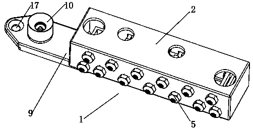
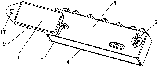
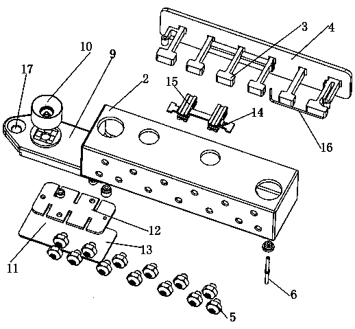
[0033] Such as Figure 1-4 As shown, a filter for an AFU antenna, the filter 1 includes a cavity 2 and a resonator 3, the side wall of the cavity 2 is open, and has a side cover 4, and the resonator 3 and the side cover 4 are integrated When forming and assem...


PUM


Abstract

The invention relates to an AFU (Antenna-Filter Unified) antenna and a filter thereof. Radio frequency ports of the antenna are moved from a coupling PCB to filters, and the filters are arranged in two columns on a PCB of a coupling calibration network in a mirroring manner. The area of the PCB is reduced without changing the relative positions of the radio frequency ports of the AFU. A resonanceplate and one side of a cavity of each filter are integrally formed, which reduces the assembly difficulty. A low-pass assembly adopts a PCB micro-strip line, and has high precision and a diversifiedstructure.

Description

technical field [0001] The invention relates to the technical field of communication equipment, in particular to an AFU antenna and a filter thereof. Background technique [0002] 5G large-scale antenna system architecture, such as Figure 8 , including a dense radiation array, a power division network, a coupling calibration network, blind-mating connectors, and a transceiver unit. The dense radiation array is formed by a number of dual-polarized radiation units according to a certain horizontal and vertical spacing; in order to reduce the cost of the dense array Mutual coupling effect, improve the direction of each RF channel Figure 1 Consistency and port isolation, decoupling devices are designed in the dense radiation array; the power division network excites and configures the amplitude and phase of a group of radiation units contained in each unit module, and the number of radiation units excited by each power division network 1. The distance between the radiating un...

Claims


Application Information

Patent Timeline
Patent Type & Authority Applications(China)
IPC IPC(8): H01P1/207H01Q23/00
CPCH01P1/207H01Q23/00
Inventor 方锋明彭蛟成钢陈志军
Owner TONGYU COMM INC
Why Eureka
Try Eureka