
A long-life slip ring based on rolling-slip combination

A long-life, confluence ring technology, applied in the field of confluence rings, can solve the problems of short service life and high processing requirements of the confluence rings, and achieve the effects of reliable operation, low processing requirements and stable operation.

Active Publication Date: 2020-12-01
CHINA ELECTRONIC TECH GRP CORP NO 38 RES INST
View PDF4 Cites 0 Cited by
  • Summary
  • Abstract
  • Description
  • Claims
  • Application Information

AI Technical Summary

Problems solved by technology

[0003] The technical problem to be solved by the present invention is: in the prior art, the service life of the confluence ring is short and the processing requirements are high

Method used


Image

  • A long-life slip ring based on rolling-slip combination
  • A long-life slip ring based on rolling-slip combination
  • A long-life slip ring based on rolling-slip combination

Examples


Embodiment Construction

[0047]The present invention will be described in detail below in conjunction with the accompanying drawings.

[0048] In the description of the present invention, it should be noted that the orientation or positional relationship indicated by the terms "upper", "lower", "inner", "outer" and the like are based on the orientation or positional relationship shown in the accompanying drawings, and are only for It is convenient to describe the present invention and simplify the description, but does not indicate or imply that the device or element referred to must have a specific orientation, be constructed and operate in a specific orientation, and thus should not be construed as limiting the present invention. In addition, the terms "first" and "second" are used for descriptive purposes only, and should not be understood as indicating or implying relative importance.

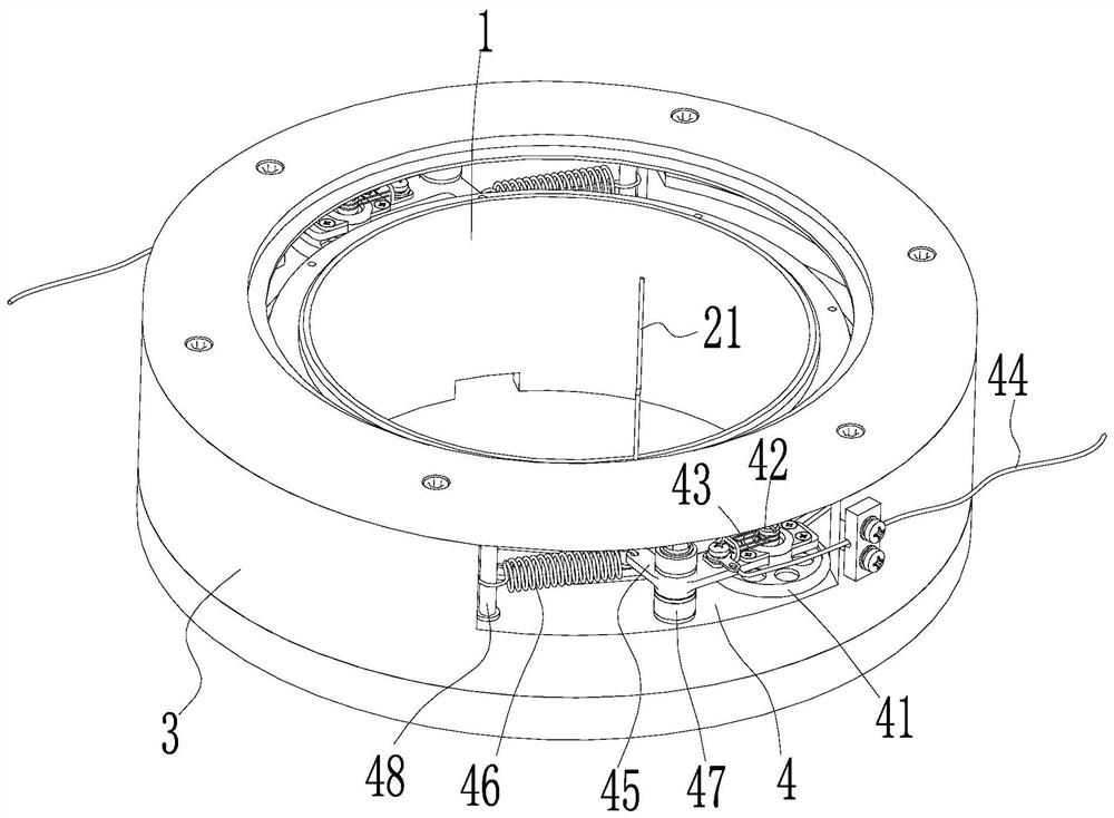
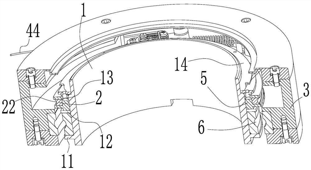
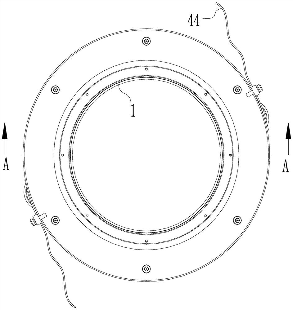
[0049] comprehensive reference Figure 1-5 , a long-life slip ring based on rolling-slip combination, including...


PUM


Abstract

The invention relates to the current of collector rings, and specifically relates to a long-life collector ring based on rolling-sliding combination. The long-life collector ring comprises an inner ring, wherein the outer circumferential surface of the inner ring is provided with a conducting ring, and an inner wire is led out from the conducting ring. The long-life collector ring further comprises an outer ring which is coaxially arranged on the outer side of the inner ring, and the inner ring is rotatably arranged on the outer ring; the outer ring is provided with a roller brush wire assembly, the roller brush wire assembly comprises a roller which is pressed on the outer ring surface of the conducting ring and can rotate relative to the outer ring surface of the conducting ring. The roller brush wire assembly further comprises a leading-out shaft which is fixedly arranged on the axis of the roller and is parallel to the axis of the conducting shaft, the leading-out shaft is sleevedwith a brush wire, and an outer wire is lead out from the brush wire. The long-life collector ring has the advantages that the life of the collector ring in the scheme is longer than that of the collector ring with a conventional structure, the processing requirement of the collector ring on parts is lower than that of the parts in the prior art, the structure is simpler, the stability is good, and the operation is reliable.

Description

technical field [0001] The invention relates to the field of slip rings, in particular to a long-life slip ring based on rolling-slip combination. Background technique [0002] Slip rings are widely used in aerospace, aviation, navigation, medical and various precision instrument fields, and are the core components of high-precision turntables. Its function is to realize the transmission of electric power or electric signal between two relatively continuous rotating parts, and avoid the winding and twisting of wires during relative rotation. The existing sliding slip ring technology is relatively mature and is widely used on various turntables, but the sliding electrical contact pair of the sliding slip ring inevitably has friction and wear, especially for large vias and large diameter slip rings. The increase of the sliding distance between the brush filament group and the conductive ring for one rotation relative to each other makes it difficult to guarantee the service l...

Claims


Application Information

Patent Timeline
Patent Type & Authority Patents(China)
IPC IPC(8): H01R39/64
CPCH01R39/64
Inventor 郑传荣徐非骏何张强张腊梅张瑞珏王贺李付军李旺李红桑青华吴后平程翔宇周杨杨帆
Owner CHINA ELECTRONIC TECH GRP CORP NO 38 RES INST
Learn More