
Efficient direct-current generator

A DC generator, high-efficiency technology, applied in the direction of DC commutators, electrical components, electromechanical devices, etc., can solve the problems of DC generator structure complexity, energy loss, etc., to improve power generation efficiency, increase power generation, and reduce load Effect

Inactive Publication Date: 2019-10-25
夏玉峰
View PDF10 Cites 0 Cited by
  • Summary
  • Abstract
  • Description
  • Claims
  • Application Information

AI Technical Summary

Problems solved by technology

Traditional generators generally generate alternating current, which needs to be converted into positive and negative DC electromotive force on the positive and negative brushes through the commutator and brushes, which makes the structure of the DC generator complex, and there is energy loss during the conversion process (the efficiency is 80%)

Method used


Image

  • Efficient direct-current generator
  • Efficient direct-current generator
  • Efficient direct-current generator

Examples


Embodiment

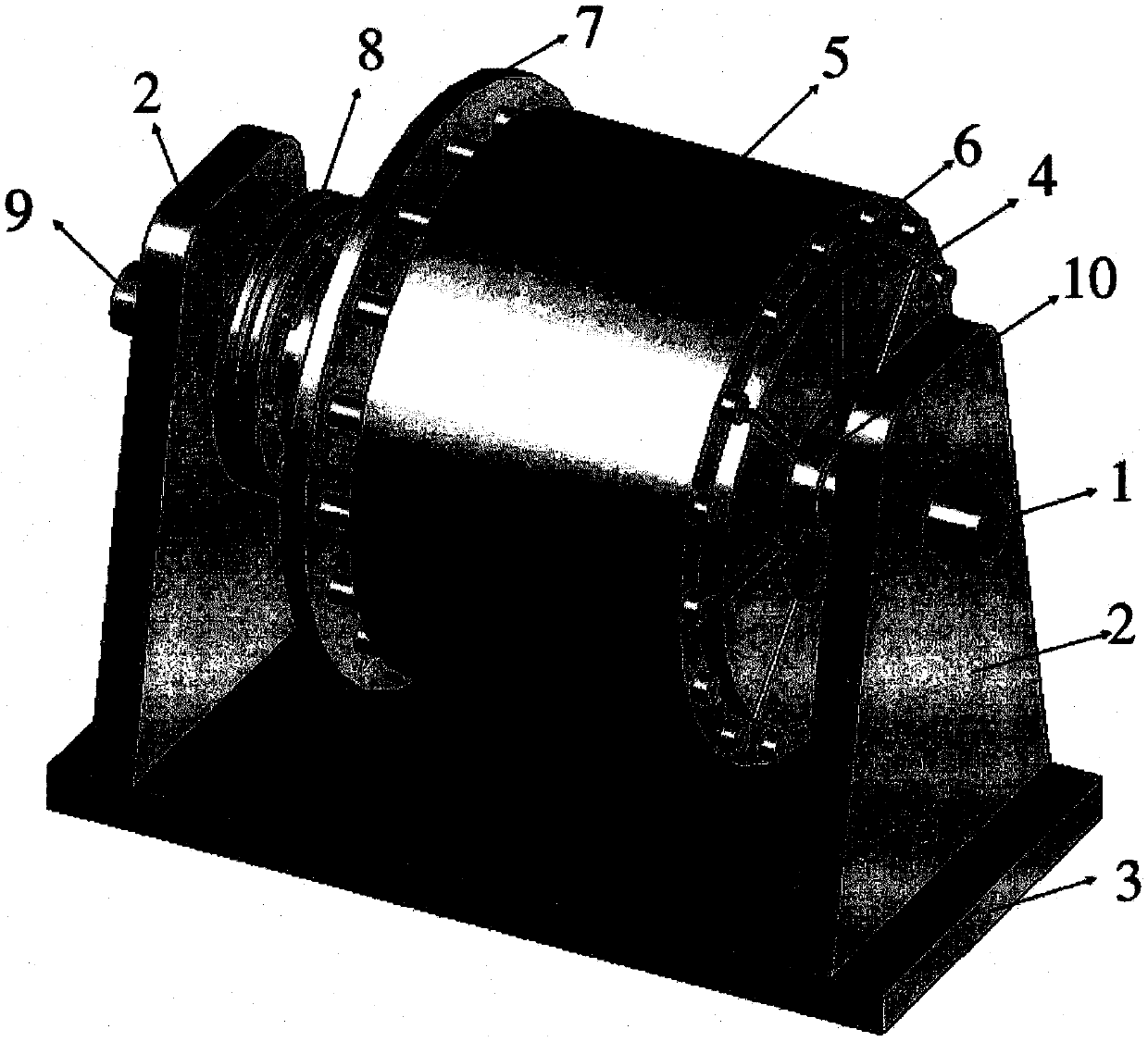
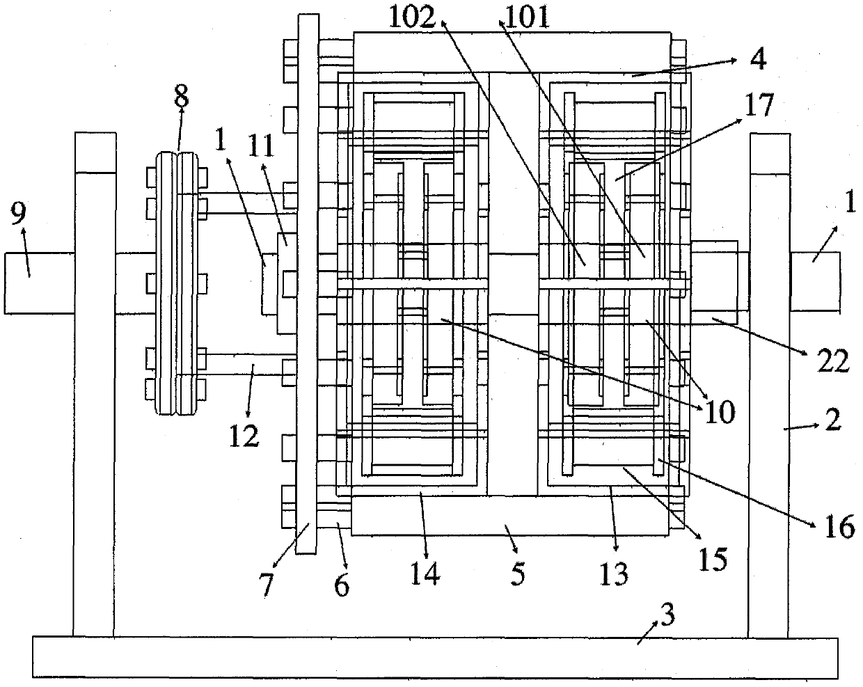
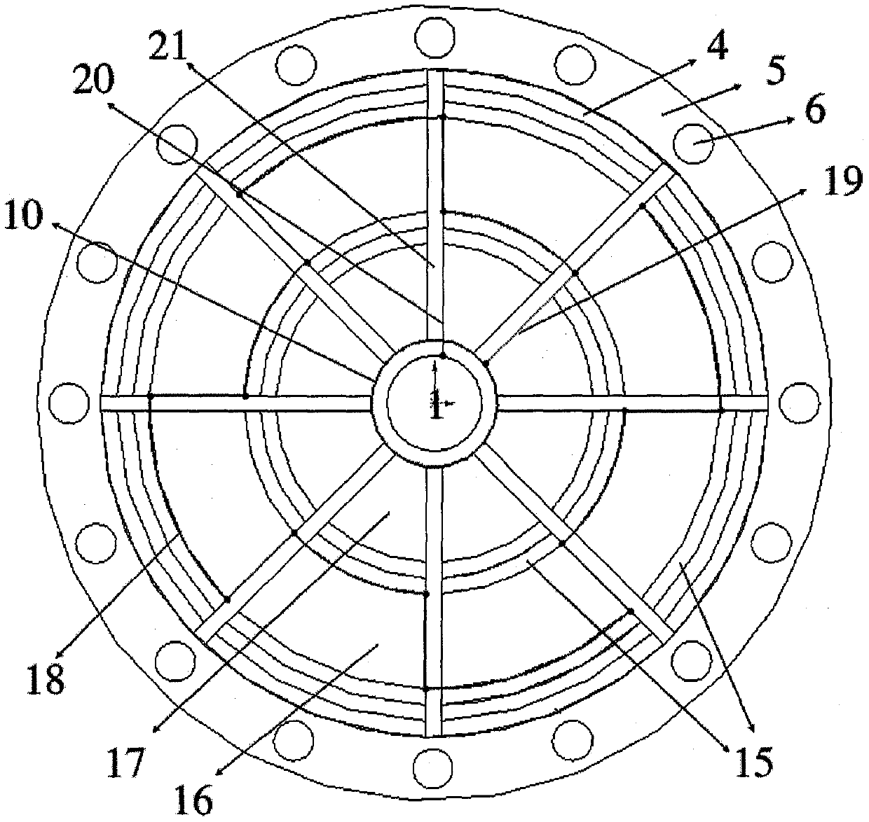
[0027] The overall structure of a high-efficiency DC generator is as follows: figure 1 As shown, the generator shown in this figure is a single-turn two-stage generator. For other details, see figure 2 to Figure 4 . The generator is fixed on the base 3 through the support frame 2, the coil axis 1 and the magnetic field axis 9 are coaxially fixed on the support frame, and the coil axis 1 and the magnetic field axis 9 are respectively driven to rotate in opposite directions by external force, and a uniform magnetic field is produced by the horseshoe magnet 4 , In the present embodiment, 8 horseshoe-shaped magnets are constructed into a single-circle annular magnetic field, and the directions of the magnetic fields of adjacent horseshoe-shaped magnets are opposite (see Figure 4 ), there are narrow gaps 21 therebetween, and all horseshoe magnets are fixed by the magnetic field cover 5 . In order to drive the ring-shaped magnetic field circle to rotate, the connecting rod 6 ...


PUM


Abstract

The invention relates to an efficient direct-current generator, which comprises a base, a support frame, conductors, an induction coil, an annular magnetic field ring, bracing poles, a magnetic fieldcover, circular brushes, a coil shaft, a magnetic field shaft, bearings, and the like. The annular magnetic field ring is formed by arranging a plurality of horseshoe magnets in a circle, and the magnetic field directions of adjacent magnets are opposite. The induction coil is composed of multiple turns of wires, and cuts magnetic induction lines in a uniform magnetic field formed by the magnets.The coil is wound on the bracing poles in a concave-convex shape, and the bracing poles brace the induction coil and are connected with the coil shaft at the center so as to transfer power and push the coil to rotate. The magnetic field cover is arranged around the annular magnetic field ring to fix the annular magnetic field ring, and pushes the annular magnetic field ring to rotate through connection with the magnetic field shaft. The annular magnetic field ring and the induction coil rotate in opposite directions to increase the relative speed and generate huge induction electromotive force, and form a closed circuit through a wire to generate a current. The circular brushes are connected with the wire to transfer the current out, so as to generate stable direct-current power.

Description

technical field [0001] The invention belongs to the technical field of generators, and in particular relates to a novel high-efficiency DC generator. Background technique [0002] At present, due to the massive growth of population and the rapid development of society, the human demand for energy has increased dramatically. According to statistics, in 2017, the total power generation in the world reached 25,551.28 billion kwh, of which China generated 6,495.14 billion kwh, accounting for a quarter of the global power generation, ranking first in the world, equivalent to the United States and Russia. The sum of the power generation of these three countries, Japan and Japan, shows that China's power generation is astonishing. [0003] The traditional generator is a device that converts mechanical energy into electrical energy. Its principle is Faraday's law of electromagnetic induction, that is, a closed coil cutting the magnetic induction line in a magnetic field will genera...

Claims


Application Information

Patent Timeline
IPC IPC(8): H02K23/04
CPCH02K23/04
Inventor 夏玉峰
Owner 夏玉峰
Learn More