
Hot-press conversion vapor chamber

A technology of temperature equalization plate and main board, which is applied in indirect heat exchangers, lighting and heating equipment, cooling/ventilation/heating renovation, etc. problem, to achieve the effect of sufficient heat transfer process, avoiding stable laminar flow, and high heat transfer efficiency

Active Publication Date: 2020-04-17
陈肃蓓
View PDF1 Cites 0 Cited by
  • Summary
  • Abstract
  • Description
  • Claims
  • Application Information

AI Technical Summary

Problems solved by technology

[0005] The purpose of the present invention is to provide a heat-press conversion vapor chamber, which changes the flow direction of the liquid by setting a buffer return channel and a diversion channel, and solves the problem of dividing the existing partition into multiple uniformly distributed and penetrating vapor chambers. The through flow path inside the body has the defect of poor heat transfer efficiency
[0006] The purpose of the present invention is to provide a heat-pressure conversion vapor chamber. By setting spoiler balls and horn holes, the lateral flow of the working fluid process can be increased, and the stable laminar flow can cause the diversion holes of the partition to be rarely used. , the analysis found that only less fluid passes through the deflector, which reduces the defect of heat transfer efficiency

Method used

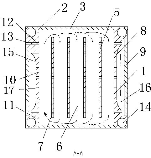

Image

  • Hot-press conversion vapor chamber
  • Hot-press conversion vapor chamber
  • Hot-press conversion vapor chamber

Examples


Embodiment 1

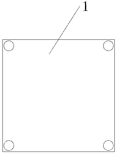
[0028] Such as figure 1 , figure 2 with image 3 As shown, a thermo-compression conversion chamber provided by the present invention includes: a rectangular main board 1, the main board is provided with a sealing port 2 above and below, and a matching sealing strip 3 is installed on the sealing port. A cavity 4 is provided in the main board; a plurality of first deflectors 5 arranged side by side with the sides of the main board are arranged in the cavity, and a plurality of first deflectors divide the inner cavity into a plurality of deflectors. Channel 6; the two ends of the first deflector plate form a gap with the corresponding inner wall of the cavity; the first deflector plate is provided with a plurality of first guide holes 7; the left and right sides of the main board have inner plates 8 And the outer heat conduction plate 9 for contacting the heat source, the inner plate includes a second deflector 10 and two ends 11, the two ends of the second deflector are used ...

Embodiment 2

[0032] Such as Figure 4As shown, the difference between Embodiment 2 and Embodiment 1 is that a spherical rotatable spoiler ball 18 is installed in the first guide hole, and the two ends of the spoiler ball partially protrude outward from the first guide hole. In the baffle, the inner side wall of the first diversion hole is a curved surface compatible with the spoiler ball, and the spoiler ball is provided with a horn hole 19, and the inner diameter of one end of the horn hole is larger than the inner diameter of the other end. The outer side of the larger end of the horn hole is provided with a spoiler 20, the curvature of the outer surface of the spoiler is greater than the curvature of the inner surface; The steering limit piece 21 in the direction of the flow plate.

[0033] When this embodiment is implemented, the fluid passes through the first diversion hole, and the turbulent flow produced by the spoiler ball avoids a stable laminar flow, and at the same time makes i...


PUM


Abstract

The invention provides a hot-pressing conversion uniform temperature plate, and the uniform temperature plate comprises a main plate, wherein a cavity is formed in the main plate, a plurality of firstflow guide plates which are arranged in parallel with the side edge of the main plate are arranged in the cavity, and the inner cavity is divided into a plurality of flow guide channels by the plurality of first flow guide plates. A plurality of first flow guide holes are formed in the first flow guide plates, and an inner side plate and an outer side heat conduction plate for contacting a heat source are arranged at the left and right sides of the main plate. The inner side plate comprises a second guide plate, and end heads are arranged at two ends of the second guide plate. The outer sideface of the inner side plate is provided with an inwards-concave mounting groove, and the two ends of the outer side heat conduction plate are fixed to the two ends of the mounting groove, wherein a gap is formed between the groove bottom of the mounting groove and the outer side heat conduction plate to form a buffer backflow channel, and the groove bottom of the mounting groove is provided witha plurality of second flow guide holes used for communicating the buffer backflow channel with the flow guide channels. The buffer backflow channel and the flow guide channel which communicate with each other and are used for making contact with a heat source are arranged, so the heat transfer process is more sufficient, and the heat transfer efficiency is higher.

Description

technical field [0001] The invention relates to the field of uniform temperature plate equipment, in particular to a thermal pressure conversion uniform temperature plate. Background technique [0002] At present, the vapor chamber is named according to the main characteristics of the components. According to the principle of using the latent heat of the working fluid in phase change to transport a large amount of heat for heat transfer, it can be classified as a flat heat pipe. Also based on this principle, it can also be It is called a vapor chamber or steam sheet, etc. The application range of the vapor chamber: it is especially suitable for heat dissipation requirements in a narrow space environment where the height space is strictly limited. When the current heat-pressure conversion vapor chamber is partially heated, the cooling liquid in the corresponding through-flow path will be heated and heated up. Since the cooling liquid is filled and sealed in the through-flow p...

Claims


Application Information

Patent Timeline
Patent Type & Authority Patents(China)
IPC IPC(8): H05K7/20F28D15/04
CPCF28D15/04H05K7/20336
Inventor 陈肃蓓於贻鹏陈益李兆增
Owner 陈肃蓓
Learn More