

Method for forming liquid rubber composite node with pipe body flow channel and node
A technology of liquid rubber and tube body, which is applied in the direction of hydraulic spring, shock absorber-spring combination, shock absorber, etc., can solve the problems that are difficult to realize, and achieve the effect of improving reliability, optimizing product performance, and improving performance
- Summary
- Abstract
- Description
- Claims
- Application Information
AI Technical Summary
Problems solved by technology
Method used
Image

Examples
Embodiment 1
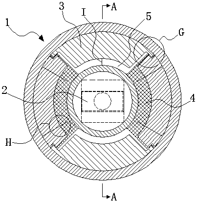
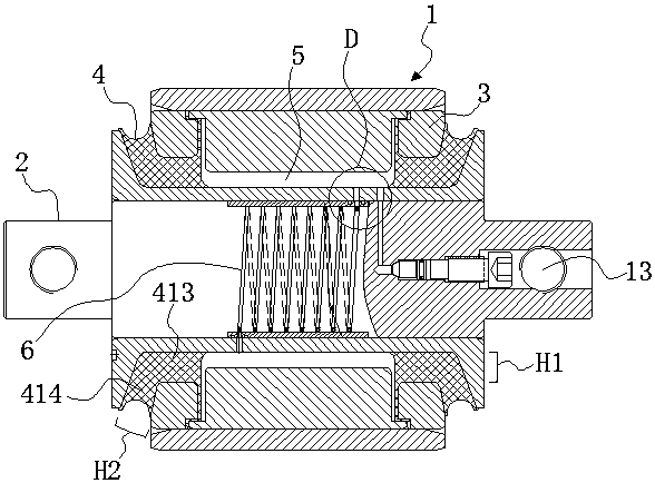
[0040] Embodiment 1: as figure 1 and figure 2 As shown, a method for forming a liquid rubber composite node with an inner groove flow path, which is to add an intermediate spacer 3 between the outer casing 1 and the mandrel 2, and bond the intermediate spacer 3 and the mandrel 2 through rubber 4 vulcanization. Connect together, and then assemble the integrated intermediate spacer and mandrel into the outer casing 1; set the pipe body flow channel in the mandrel 2, and hollow out multiple spaces on the middle spacer 3. After vulcanization, use The rubber 4 and the plurality of spaces form a plurality of liquid cavities 5 that are independent of each other. Liquids (not shown in the figure) are arranged in the plurality of liquid cavities 5, and the plurality of liquid cavities 5 pass through pipe flow channels. 6 phases are connected. The liquid rubber composite joint formed by the above method can provide smaller radial stiffness and greater axial stiffness, and achieve a l...
Embodiment 2
[0057] Embodiment 2: as Figure 11 As shown, compared with the embodiment 1, the difference of the present embodiment is that: the two ends of the coat 1 in the present embodiment adopt the cuff buckle design structure. One end of the intermediate spacer 3 is provided with a continuous step portion 14 and a step portion 2 15, the step portion 14 is located at the lower position (close to the mandrel), and the step portion 2 15 is located at the upper position (away from the mandrel) position), one end face of the jacket 1 is vertically flush with the lateral vertical surface of the step part 2 15, and an end sealing ring 16 is placed on the step part 2 15. When the flange is not crimped, the end sealing ring The height of 16 is higher than the height of step part 2 15, that is, the end sealing ring 16 is located between the step part 2 15 and the outer casing 1. A jacket flanging part 112 is extended on one end surface of the jacket 1. During the flanging operation, the end s...
PUM
 Abstract
Description
Claims
Application Information