
Reversible high-rigidity rotating shaft system device driven by air turbine

A technology of air turbine and rotary shaft system, which is applied in transmission devices, fluid transmission devices, belts/chains/gears, etc. It can solve the problems of reduced rotation accuracy, high price, and difficulty in ensuring the coaxiality of the motor shaft and the rotary shaft. Achieve the effect of reducing volume and movement quality and improving movement precision

Pending Publication Date: 2019-10-29
JIANGSU JITRI JINGKAI HIGH VALUE MFG CO LTD
View PDF0 Cites 1 Cited by
  • Summary
  • Abstract
  • Description
  • Claims
  • Application Information

AI Technical Summary

Problems solved by technology

The slewing bearings used in the existing machine tool slewing shaft devices are generally mechanical bearings or ceramic bearings, which are contact bearings, which will inevitably cause friction with the sle Most of the rotary shaft devices are driven by motors. In addition to being expensive, it is difficult to ensure the coaxiality between the motor shaft and the rotary shaft, which affects the dynamic performance of the rotary shaft and reduces the rotation accuracy. In addition, the high-speed rotation of the motor shaft will generate a lot of heat. , which in turn causes thermal deformation of the shafting

Method used


Image

  • Reversible high-rigidity rotating shaft system device driven by air turbine
  • Reversible high-rigidity rotating shaft system device driven by air turbine
  • Reversible high-rigidity rotating shaft system device driven by air turbine

Examples


Embodiment Construction

[0022] The preferred embodiments of the present invention will be described in detail below in conjunction with the accompanying drawings, so that the advantages and features of the present invention can be more easily understood by those skilled in the art, so as to define the protection scope of the present invention more clearly.

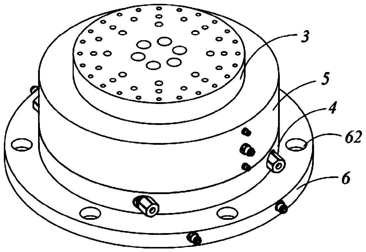
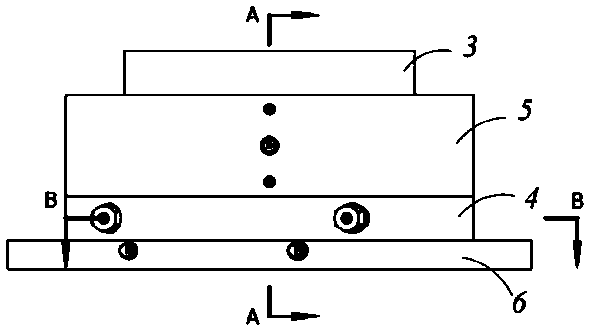
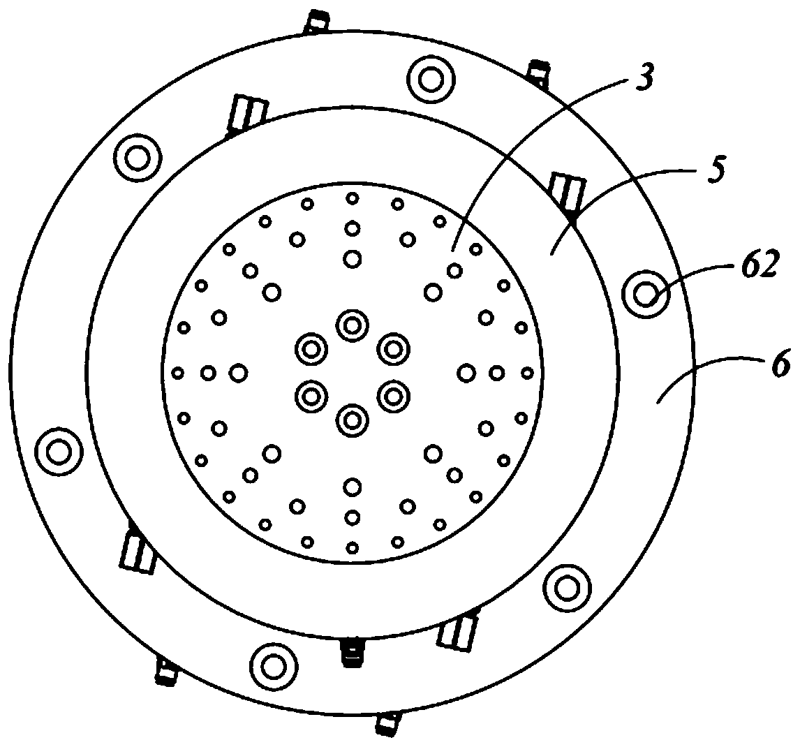
[0023] refer to Figure 1~5 , the embodiment of the present invention includes:

[0024] A reversible high-rigidity air turbine-driven rotary shafting device, using an air turbine 1 to drive a rotating shaft 2 to rotate, and the rotating shaft 2 is positioned and installed in an air bearing 5 by an upper thrust plate 3 and a lower thrust plate 4, specifically , the upper end surface of the rotating shaft 2 is fixedly connected with the upper thrust plate 3 through a positioning pin, the lower end surface of the rotating shaft 2 is fixedly connected with the lower thrust plate 4 through a positioning pin, and the air bearing 5 is embedded in the u...


PUM


Abstract

The invention discloses a reversible high-rigidity rotating shaft system device driven by an air turbine. According to the device, a rotary shaft is driven to rotate by the air turbine and is fixedlymounted in an air bearing through an upper thrust plate and a lower thrust plate; the air bearing is in clearance fit with the rotary shaft, the upper thrust plate and the lower thrust plate; the airturbine is integrated to the circumferential wall of the lower thrust plate and comprises an anticlockwise-rotating air turbine body and a clockwise-rotating air turbine body, and high-pressure gas drives the anticlockwise-rotating air turbine body and the clockwise-rotating air turbine body to rotate so as to drive the rotary shaft and the upper thrust plate to rotate clockwise or anticlockwise.Accordingly, with the adoption of full gas lubrication and gas driving, use of motors is avoided, the cost is reduced, the structure is more compact, and the volume and the motion mass of the whole motion shaft system are reduced effectively due to the fact that the air turbine and the lower thrust plate are integrated; additionally, gas can also cool the shaft system, temperature rise is furthercontrolled, and the motion accuracy of the shaft system is improved effectively.

Description

technical field [0001] The invention relates to the technical field of precision numerical control machine tools, in particular to a reversible high-rigidity air turbine-driven rotary shafting device. Background technique [0002] Rotary shaft devices are widely used in precision CNC machine tools, and their performance directly determines the machining accuracy of CNC machine tools. The slewing bearings used in the rotary shafting devices of existing machine tools are generally mechanical bearings or ceramic bearings. Most of the rotary shaft devices are driven by motors. In addition to being expensive, it is difficult to ensure the coaxiality between the motor shaft and the rotary shaft, which affects the dynamic performance of the rotary shaft and reduces the rotation accuracy. In addition, the high-speed rotation of the motor shaft will generate a lot of heat. , which in turn causes thermal deformation of the shafting. Contents of the invention [0003] The technical...

Claims


Application Information

Patent Timeline
Patent Type & Authority Applications(China)
IPC IPC(8): F16H41/24F16H41/30B23Q5/00B23Q11/12
CPCF16H41/24F16H41/30B23Q5/00B23Q11/12
Inventor 陈万群霍德鸿滕翔宇丁辉陈高强
Owner JIANGSU JITRI JINGKAI HIGH VALUE MFG CO LTD
Learn More