Aircraft monocular visual scale estimation method and device, aircraft navigation system and aircraft
A technology of monocular vision and scale estimation, which is applied in the field of aircraft and can solve problems such as inability to achieve
Active Publication Date: 2019-10-29
BEIJING JINGDONG SHANGKE INFORMATION TECH CO LTD +1
5 Cites 0 Cited by
AI-Extracted Technical Summary
Problems solved by technology
Many scholars have conducted research in this area. For example, the classic algorithm PTAM (Parallel Tracking and Mapping, Tracking and Drawing) in monocular vision SLAM uses artificial operations to estimate the scale, and translates and fixes...
Method used
With formula (11) multiplied by Δtk and formula (10) multiplied by Δtk-1 subtraction, can obtain the speed difference between two consecutive frames, thereby simplifying the process of solving IMU speed:
[0065] In one embodiment, the distance detection sensor takes an ultrasonic sensor as an example, which uses ultrasonic pulses to detect objects and uses its echoes to measure...
Abstract
The present disclosure proposes an aircraft monocular visual scale estimation method and device, an aircraft navigation system and an aircraft, and relates to the technical field of aircrafts. The aircraft monocular visual scale estimation method of the present disclosure includes the steps of: acquiring a current flight height estimated value; and detecting, based on the detected data of a vertically downward detecting distance detection sensor and the detected data of an inertial measuring unit (IMU) when the flight height estimated value is less than a predetermined height, a monocular visual scale value. In this way, when the flight height of the aircraft is less than the predetermined height, the distance detecting sensor and the IMU can obtain the monocular visual scale value in cooperation. On the one hand, manual intervention is not required and the degree of automation is improved, on the other hand, the advantages of the distance detection sensor and the IMU can be integratedin order to reduce errors caused bya single measurement method and improve the accuracy of scale estimation.
Application Domain
Navigational calculation instrumentsNavigation by speed/acceleration measurements
Technology Topic
Flight vehicleFlight height +9
Image
Examples
- Experimental program(1)
Example Embodiment
[0043] The technical solutions of the present disclosure will be further described in detail below through the accompanying drawings and embodiments.
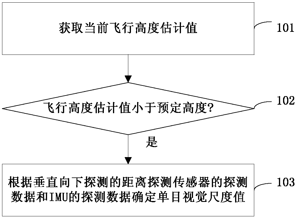
[0044] The flow chart of an embodiment of the method for estimating the monocular visual scale of an aircraft of the present disclosure is as follows: figure 1 Shown.
[0045] In step 101, an estimated current flying height is obtained. In an embodiment, the estimated flying height may be obtained by a distance detection sensor installed on the aircraft with a detection direction vertically downward. When the flight altitude exceeds the measurement range of the sensor and detection is impossible, the estimated flight altitude may be a predetermined threshold value by default, and the predetermined threshold value is higher than the predetermined altitude in step 102.
[0046] In step 102, the estimated flying altitude is compared with a predetermined altitude. Step 103 is executed when the estimated flying height is less than the predetermined height. In one embodiment, altitude detection and comparison can be performed continuously. When the estimated value of the flight altitude changes from the predetermined altitude, the mode switching is determined when the state is stabilized for a predetermined period of time, so as to avoid accidental phenomena causing repeated mode switching.
[0047] In step 103, the monocular vision scale value is determined according to the detection data of the vertical downward detection distance detection sensor and the detection data of the IMU. In one embodiment, the detection data of the distance detection sensor and the detection data of the IMU can be used to obtain the monocular vision scale values in two ways, and then the two can be fused and calculated.
[0048] In one embodiment, the predetermined height can be in the range of 15-100 meters, and is adjusted according to the performance and model of the distance detection sensor, and the flight speed of the aircraft. If the distance detection sensor is an ultrasonic sensor, the predetermined height is preferably 20 meters . In an embodiment, the distance detection sensor includes one or more of an ultrasonic sensor, a lidar or a millimeter wave radar. In an embodiment, the setting of the predetermined height may be positively correlated with the detection wave speed of the distance detection sensor and negatively correlated with the flight speed of the aircraft.
[0049] Through this method, when the flying height of the aircraft is less than the predetermined height, the distance detection sensor and the IMU can be used to obtain the monocular visual scale value. On the one hand, it does not require manual intervention and improves the degree of automation. On the other hand, it can also Combining the advantages of distance detection sensors and IMU, reducing errors caused by a single measurement method, and improving the accuracy of scale estimation.
[0050] The flowchart of another embodiment of the method for estimating the monocular visual scale of an aircraft of the present disclosure is as follows: figure 2 Shown.
[0051] In step 201, an estimated value of the current flying height is obtained.
[0052] In step 202, the estimated flying altitude is compared with a predetermined altitude. Step 203 is executed when the estimated flying height is less than the predetermined altitude; otherwise, step 206 is executed.
[0053] In step 203, the scale estimation value of the SLAM algorithm is obtained according to the detection data of the distance detection sensor as the first scale factor.
[0054] In one embodiment, the height change detected by the distance detection sensor may be obtained first according to the output frequency of the SLAM algorithm, and then the height change detected by the distance detection sensor, and the height change determined by the ORB-SLAM algorithm, based on the weighted least square Multiplication determines the monocular vision scale value, where the closer the generated event is to the current moment, the greater the weight of the data.
[0055] In step 204, the scale estimation value of the SLAM algorithm is obtained according to the detection data of the IMU as the second scale factor.
[0056] In one embodiment, the IMU pose information may be obtained first according to the output frequency of the SLAM algorithm, the pose change of the IMU statistics between the collection moments of any two adjacent frames of monocular images may be determined, and then the pose statistics of the IMU may be determined. The changes, as well as the posture changes determined by the ORB-SLAM algorithm, are based on the least square method to determine the monocular vision scale value.
[0057] In step 205, based on the scale factor fusion strategy, the monocular vision scale value is determined according to the first scale factor and the second scale factor, and then returns to step 201 for continuous detection.
[0058] In one embodiment, according to the formula:
[0059] λ=λ 1 *θ 1 +λ 2 *θ 2
[0060] Determine the monocular vision scale value λ, where λ 1 Is the first scale factor, λ 2 Is the second scale factor, θ 1 Is the weight of the first scale factor, θ 2 Is the weight of the second scale factor, θ 1 It is positively correlated with the ratio of the confidence of the distance detection sensor to the sum of the confidence of the distance detection sensor and the IMU, θ 1 And θ 2 Is a positive number, and θ 1 +θ 2 = 1.
[0061] In step 206, according to the detection data of the IMU, an algorithm similar to that in step 204 is used to obtain the scale estimation value of the SLAM algorithm as the monocular vision scale value, and then return to step 201 for continuous detection.
[0062] Through this method, it is possible to integrate the detection results of the distance detection sensor and the IMU when the flying height is low, and improve the accuracy; at the same time, when the flying height of the aircraft suddenly rises, it can switch to only use the IMU detection results for scale estimation Since the calculation of the scale estimate based on the detection data of the IMU is always in the calculation, the efficiency of handover can be ensured, and the accuracy of the scale estimation at the handover time can also be improved, preventing the calculation based on the IMU detection result from starting suddenly and causing the initial information to be inaccurate , Which will continue to affect the accuracy of scale estimation.
[0063] In one embodiment, θ 1 , Θ 2 The value of can be a predetermined fixed value set according to equipment performance; θ 1 , Θ 2 It can also be variable, where θ 1 Decrease as the height of the aircraft increases. When the estimated flying height of the aircraft is higher than the predetermined height, θ 1 = 0, θ 2 = 1.
[0064] Through this method, the detection accuracy of the distance detection sensor can be taken into account that when the height reaches a certain height, as the height increases, the dependence on the distance detection sensor is gradually reduced, and the weight of the IMU detection result can be increased. It will further improve the accuracy of the scale estimation when the flight altitude is lower than the predetermined altitude, and at the same time, it can provide a more accurate base value when the flight altitude rises to the predetermined altitude, thereby further improving the accuracy of the scale estimation.
[0065] In one embodiment, the distance detection sensor takes an ultrasonic sensor as an example. The ultrasonic pulse is used to detect an object and its echo is used to measure the distance of the object, which can be used for distance measurement, target recognition, and obstacle avoidance. Ultrasonic sensors are small in size, light in weight, low in power consumption, low in price, and the working environment is rarely restricted. Ultrasonic sensors can be installed under the aircraft body to detect downwards in order to measure the height of the aircraft.
[0066] When the flying altitude of the aircraft is low (for example, less than 20 meters), such as during the take-off phase of the aircraft (that is, the initialization phase of the monocular ORB-SLAM algorithm), the altitude value of the aircraft can be measured. In order to obtain a more robust scale estimation result, the more observations, the better. Therefore, during the take-off phase of the aircraft, the altitude changes as much as possible.
[0067] For example, in the take-off phase, the monocular ORB-SLAM algorithm can obtain the estimated value of the altitude difference z of the aircraft in a fixed time interval. i At the same time, the ultrasonic sensor can also measure the altitude difference h of the aircraft in the same time interval i. Since the height measured by the ultrasonic sensor is the absolute height relative to the ground, the scale λ approximately satisfies h i /z i. The measurement noise of the ultrasonic sensor approximately obeys the Gaussian distribution, and the measurement error caused by noise can be reduced through multiple sets of data samples. After obtaining a series of sample data {(z 1 , H 1 ),(z 2 , H 2 ),…,(z n , H n )} After that, the least square method can be used to process the data and solve the scale.
[0068] For the function of model h=λz, perform parameter estimation, after obtaining a series of sample data, use the least square method to estimate. When the measurement noise presents a Gaussian distribution, the least squares estimation can be used to realize unbiased estimation.
[0069] Least squares estimation is to obtain the best estimate by minimizing the sum of squares of errors. Suppose there are n sets of independent observations (z 1 , H 1 ),(z 2 , H 2 ),…,(z n , H n ), then according to the relationship between scale and height:
[0070]
[0071] Among them, λ is the parameter to be estimated, ε 1 , Ε 2 ,..., ε n It is the error value and independent of each other. The purpose of the least square method is to estimate an optimal scale estimate Minimize the sum of squares of its error:
[0072]
[0073] For the best Derivation of formula (2):
[0074]
[0075] The optimal estimate of λ can be obtained by setting the derivative to zero:
[0076]
[0077] In practical applications, the scale of the monocular ORB-SLAM algorithm drifts, and different weights need to be applied to the data measured in different time periods. Give the nearest measured value a larger weight, and the weight of the measured value at the historical moment is appropriately reduced. The weighted least square method is used to realize the scale estimation, that is, the weight w is added when calculating the residual square sum, as shown below:
[0078]
[0079] Also according to the above method, the final estimated value obtained by the weighted least square method can be obtained:
[0080]
[0081] The weighting process can make the current measured value account for a larger proportion in the entire parameter estimation process, and it can also eliminate the impact of the monocular ORB-SLAM algorithm scale drift to a certain extent. Through many experiments, it is found that the scale estimation error obtained by this method is small, and the stability is strong, and the scale estimation can be carried out on the aircraft in real time. Due to the limitation of the ultrasonic sensor ranging range, there are certain constraints on the flying height of the aircraft when using this method for scale estimation. If the flying height of the aircraft exceeds the ultrasonic ranging range, the scale estimation will be invalid. At the same time, when using an ultrasonic sensor to measure height, it is necessary to ensure that the ground is level and free of obstructions to ensure that sound waves can be reflected smoothly for accurate measurement, especially in indoor or outdoor small scene environments to improve the accuracy of scale estimation.
[0082] In one embodiment, compared to the environmental limitation problem existing when using ultrasonic sensors for scale estimation, the algorithm for scale estimation using IMU has fewer constraints on the working environment, and is suitable for outdoor large scene environments.
[0083] The IMU can obtain the six-degree-of-freedom pose information according to its output acceleration and angular velocity. The position estimation result is related to the current speed. The IMU displacement in any time interval cannot be obtained directly from the acceleration output value. The initial integration start time must be known Speed can accurately obtain the position. When using the IMU to estimate the scale of the monocular ORB-SLAM algorithm, it is necessary to use the six-degree-of-freedom pose estimation value obtained by the IMU as the observation value to correct the visual output pose. Therefore, the pose change information of the IMU between two adjacent image frames must be obtained, which requires preprocessing of the IMU data so that it can obtain the pose change in any time interval.
[0084] Since the output frequency of the camera and IMU are not equal, for example, the output frequency of the camera is 30Hz, and the output frequency of the IMU is 200Hz, so when the pose information obtained by the IMU is used as the observation value, only the output frequency of the IMU and the visual SLAM needs to be consistent The pose output result is sufficient. It is not necessary to perform pose estimation processing for each frame of IM data, so as to avoid unnecessary waste of resources, thereby reducing the amount of data processing, reducing the requirements and burden on the equipment, and also enhancing Correspondence between IMU and visual SLAM data.
[0085] In one embodiment, the IMU data can be integrated and combined to make the output frequency of the pose and the vision consistent. According to the output frequency of the camera, the IMU data between the two input times of the camera is integrated once to obtain the pose output result. After data preprocessing, the IMU pose output frequency will be consistent with the visual output frequency.
[0086] Through the external parameter calibration of the monocular camera and IMU, the pose relationship between the two (p c i , Q c i )A known. According to the definition of the monocular vision scale and the relative pose relationship between the monocular camera and the IMU, the relationship between the coordinates of the IMU in the world coordinate system and the coordinates of the camera in the world coordinate system can be obtained:
[0087]
[0088]
[0089] Among them, s represents the scale value, C c w Represents the direction cosine matrix between the camera coordinate system and the IMU coordinate system, (p i w , Q i w ) Is the pose estimation result of the IMU, which can be obtained by preprocessing the IMU data, (p c w , Q c w ) Is the pose estimation result without scale output by the monocular ORB-SLAM algorithm.
[0090] According to the IMU kinematics model and inertial navigation solution method, the IMU data can be preprocessed to obtain the pose calculation formula:
[0091]
[0092]
[0093]
[0094] In the above formula, k and k+1 respectively represent the moment when the image frame arrives. There will be multiple IMU data in the time interval of k and k+1, so the IMU data in the time period of k and k+1 is pre-integrated:
[0095]
[0096]
[0097]
[0098] The advantage of pre-integration processing is that each integration starts with respect to the k-th moment, and the initial value of the integration is zero. In this way, the pose change of the IMU between any two image frame moments can be obtained without introducing cumulative errors. Finally, formula (9) is inserted into (8), then formula (8) can be simplified to:
[0099]
[0100]
[0101]
[0102] In order to calculate the scale value, the formula (7) is incorporated into the formula (9), and the linear equation of the k-th image frame time on the scale s can be obtained as follows:
[0103]
[0104] In the above formula, g represents the gravity vector, △t k Represents the time interval between the kth frame and the k+1th frame, v i w (k) represents the speed of the IMU at the k-th frame time. The scale value s of the monocular ORB-SLAM algorithm can be obtained by solving the above equation.
[0105] Through the monocular ORB-SLAM algorithm and IMU solution, multiple sets of pose information can be obtained, and there is only one unknown to be solved, so the equation system is an overdetermined equation system. In order to facilitate analysis and solution, formula (11) is written as a matrix expression:
[0106]
[0107] among them, To solve the above equation, we need to get the velocity v of the IMU at each moment i w (k). This will bring about a large cumulative error. In order to avoid solving the speed value at each moment, a difference method can be used. Considering that the above linear equation can be expressed as:
[0108]
[0109]
[0110] Multiply △t by formula (11) k Multiply △t with formula (10) k-1 By subtracting, you can get the speed difference between two consecutive frames, which simplifies the process of solving the IMU speed:
[0111]
[0112] The definition of each component is as follows:
[0113]
[0114] The value of each component in the above formula is obtained by monocular ORB-SLAM and IMU pose solution, where p i c The fixed position relationship between the camera and the IMU can be obtained through external parameter calibration. p i w (k,k+1),v i w (k, k+1) respectively represent the position and velocity changes of the IMU in the time period k to k+1, which are obtained through the previous IMU pre-integration processing. p c w ,C c w Respectively represent the position and attitude of the camera, obtained by the ORB-SLAM algorithm.
[0115] From the above analysis, it can be seen that at least three frames of images are required to solve the difference. If the number of image frames is N, then the dimension of the matrix on the left side of formula (12) is 3(N-2)×1, and the number of unknowns is 1, so For the overdetermined equation, the problem of solving the equation at this time also becomes a least squares problem.
[0116] In practical applications, after the initialization of the ORB-SLAM algorithm is completed, about 100 frames of images and IMU data are selected for scale estimation, so that a better scale estimation result can be obtained without occupying too much computing resources. Realize the scale estimation of the monocular ORB-SLAM algorithm in time.
[0117] The schematic diagram of an embodiment of the aircraft monocular visual scale estimation controller of the present disclosure is as follows: image 3 Shown. The altitude estimation module 31 can obtain the current flight altitude estimation value. In one embodiment, the estimated flying height may be obtained by a distance detection sensor installed on the aircraft with a detection direction vertically downward. The scale calculation module 32 can determine the monocular vision scale value according to the detection data of the vertical downward detection distance detection sensor and the detection data of the IMU when the estimated flying height is less than the predetermined height. In one embodiment, the detection data of the distance detection sensor and the detection data of the IMU can be used to obtain the monocular vision scale values in two ways, and then the two can be fused and calculated.
[0118] Such an aircraft monocular vision scale estimation controller can obtain the monocular vision scale value by using the distance detection sensor and the IMU when the flying height of the aircraft is less than the predetermined height. On the one hand, it does not require manual intervention and improves the degree of automation. On the other hand, it can also integrate the advantages of distance detection sensors and IMUs, reduce errors caused by a single measurement method, and improve the accuracy of scale estimation.
[0119] The schematic diagram of an embodiment of the scale calculation module in the monocular visual scale estimation controller of the aircraft of the present disclosure is as follows: Figure 4 Shown.
[0120] The first scale estimation unit 421 can obtain the scale estimation value of the SLAM algorithm according to the detection data of the distance detection sensor as the first scale factor. In one embodiment, the height change detected by the distance detection sensor may be obtained first according to the output frequency of the SLAM algorithm, and then the height change detected by the distance detection sensor, and the rapid feature point extraction and description of the height change determined by the ORB-SLAM algorithm In this case, the monocular vision scale value is determined based on the weighted least squares method, where the closer the generation time to the current moment, the greater the weight.
[0121] The second scale estimation unit 422 can obtain the scale estimation value of the SLAM algorithm according to the detection data of the IMU as the second scale factor. In one embodiment, the IMU pose information may be obtained first according to the output frequency of the SLAM algorithm, the pose change of the IMU statistics between the collection moments of any two adjacent frames of monocular images may be determined, and then the pose statistics of the IMU may be determined. Changes, as well as rapid feature point extraction and description of the pose changes determined by the ORB-SLAM algorithm, determine the monocular vision scale value based on the least square method.
[0122] The fusion unit 423 can determine the monocular vision scale value according to the first scale factor and the second scale factor based on the scale factor fusion strategy.
[0123] In one embodiment, according to the formula:
[0124] λ=λ 1 *θ 1 +λ 2 *θ 2
[0125] Determine the monocular vision scale value λ, where λ 1 Is the first scale factor, λ 2 Is the second scale factor, θ 1 Is the weight of the first scale factor, θ 2 Is the weight of the second scale factor, θ 1 It is positively correlated with the ratio of the confidence of the distance detection sensor to the sum of the confidence of the distance detection sensor and the IMU, θ 1 And θ 2 Is a positive number, and θ 1 +θ 2 = 1.
[0126] In one embodiment, the scale calculation module can compare the change of the estimated flying height with the size of the predetermined height in real time. When the estimated flying height becomes greater than or equal to the predetermined height, the scale calculation module switches to the second scale estimation unit. 422 uses the scale estimation value of the SLAM algorithm obtained according to the detection data of the IMU as the monocular vision scale value; when the flying height estimation value becomes less than the predetermined height, other modules of the activated scale calculation module jointly determine the monocular vision scale value.
[0127] Such an aircraft's monocular vision scale estimation controller can comprehensively consider the detection results of the distance detection sensor and IMU when the aircraft's flying height is low, and improve the accuracy; at the same time, it can be switched to only use when the aircraft's flying height suddenly rises. The IMU detection result is scaled. Since the calculation of the scale estimation value based on the IMU detection data is always being calculated, the efficiency of handover can be guaranteed, and the accuracy of the scale estimation at the handover time can also be improved, preventing the calculation based on the IMU detection result The sudden start causes the initial information to be inaccurate, which will continue to affect the accuracy of the scale estimation.
[0128] The structural schematic diagram of an embodiment of the monocular visual scale estimation controller for the aircraft of the present disclosure is as follows: Figure 5 Shown. The monocular vision scale estimation controller of the aircraft includes a memory 501 and a processor 502. Wherein: the memory 501 may be a magnetic disk, flash memory or any other non-volatile storage medium. The memory is used to store the instructions in the corresponding embodiment of the above-mentioned method for estimating the monocular vision scale of the aircraft. The processor 502 is coupled to the memory 501 and can be implemented as one or more integrated circuits, such as a microprocessor or a microcontroller. The processor 502 is used to execute instructions stored in the memory, which can improve the automation and accuracy of the dimensional estimation.
[0129] In one embodiment, it can also be as Image 6 As shown, the aircraft monocular vision scale estimation control 600 includes a memory 601 and a processor 602. The processor 602 is coupled to the memory 601 through the BUS bus 603. The aircraft monocular visual dimension estimation controller 600 can also be connected to an external storage device 605 through the storage interface 604 to recall external data, and can also be connected to a network or another computer system (not shown) through the network interface 606. No more detailed introduction here.
[0130] In this embodiment, the data instructions are stored in the memory, and the above instructions are processed by the processor, so that the degree of automation and accuracy of the scale estimation can be improved.
[0131] In another embodiment, a computer-readable storage medium has computer program instructions stored thereon, which, when executed by a processor, realizes the steps of the method for estimating the monocular vision scale of an aircraft corresponding to the embodiment. Those skilled in the art should understand that the embodiments of the present disclosure may be provided as methods, devices, or computer program products. Therefore, the present disclosure may adopt the form of a complete hardware embodiment, a complete software embodiment, or an embodiment combining software and hardware. Moreover, the present disclosure may take the form of a computer program product implemented on one or more computer-usable non-transitory storage media (including but not limited to disk storage, CD-ROM, optical storage, etc.) containing computer-usable program codes. .
[0132] A schematic diagram of an embodiment of the aircraft navigation system of the present disclosure is as follows Figure 7 Shown. The distance detection sensor 71 may be one or more of an ultrasonic sensor, a lidar or a millimeter wave radar, and can detect the flying height of the aircraft in real time. IMU72 can detect the pose information of the aircraft. The image capture device 73 can capture monocular vision images of the ground. The aircraft monocular vision scale estimation controller 74 can be any one of the above, and can be determined in real time according to the information collected by the distance detection sensor 71, IMU 72 and the image acquisition device 73 by using any of the above aircraft monocular vision scale estimation methods The scale value of the monocular vision image. The pose calculator 75 can determine the pose of the aircraft according to the monocular vision image and the monocular vision scale value, so that the route planning device 76 determines the flight path of the aircraft according to the pose of the aircraft.
[0133] When the flying height of the aircraft is less than the predetermined height, the distance detection sensor is used in conjunction with the IMU to obtain the monocular visual scale value, which improves the accuracy of scale estimation, thereby improving the accuracy of pose determination and navigation. Improve the reliability of the flight route of the aircraft.
[0134] A schematic diagram of an embodiment of the aircraft of the present disclosure is as Figure 8 Shown. The flying equipment 81 may be equipment such as a rotor, which can drive the aircraft to fly. The energy supply device 82 can provide energy for the flight equipment. In one embodiment, the energy supply device 82 can also supply power for other parts of the aircraft, such as the aircraft navigation system 83; the aircraft navigation system 83 can be as described above Figure 7 The aircraft navigation system shown can determine the flight path and correct it in real time, thereby improving the reliability of the flight path of the aircraft.
[0135] When the flying height of the aircraft is less than the predetermined height, the distance detection sensor is used in conjunction with the IMU to obtain the monocular visual scale value, which improves the accuracy of scale estimation, thereby improving the accuracy of pose determination and navigation. Improve the reliability of the flight route of the aircraft.
[0136] The present disclosure is described with reference to flowcharts and/or block diagrams of methods, devices (systems) and computer program products according to embodiments of the present disclosure. It should be understood that each process and/or block in the flowchart and/or block diagram and the combination of processes and/or blocks in the flowchart and/or block diagram can be realized by computer program instructions. These computer program instructions can be provided to the processor of a general-purpose computer, a special-purpose computer, an embedded processor, or other programmable data processing equipment to generate a machine, so that the instructions executed by the processor of the computer or other programmable data processing equipment are generated In the process Figure one Process or multiple processes and/or boxes Figure one A device with functions specified in a block or multiple blocks.
[0137] These computer program instructions can also be stored in a computer-readable memory that can guide a computer or other programmable data processing equipment to work in a specific manner, so that the instructions stored in the computer-readable memory produce an article of manufacture including the instruction device. The device is implemented in the process Figure one Process or multiple processes and/or boxes Figure one Functions specified in a box or multiple boxes.
[0138] These computer program instructions can also be loaded on a computer or other programmable data processing equipment, so that a series of operation steps are executed on the computer or other programmable equipment to produce computer-implemented processing, so as to execute on the computer or other programmable equipment. Instructions are provided to implement the process Figure one Process or multiple processes and/or boxes Figure one Steps of functions specified in a box or multiple boxes.
[0139] So far, the present disclosure has been described in detail. In order to avoid obscuring the concept of the present disclosure, some details known in the art are not described. Based on the above description, those skilled in the art can fully understand how to implement the technical solutions disclosed herein.
[0140] The method and apparatus of the present disclosure may be implemented in many ways. For example, the method and apparatus of the present disclosure can be implemented by software, hardware, firmware or any combination of software, hardware, and firmware. The above-mentioned order of the steps for the method is for illustration only, and the steps of the method of the present disclosure are not limited to the order specifically described above, unless specifically stated otherwise. In addition, in some embodiments, the present disclosure can also be implemented as programs recorded in a recording medium, and these programs include machine-readable instructions for implementing the method according to the present disclosure. Thus, the present disclosure also covers a recording medium storing a program for executing the method according to the present disclosure.
[0141] Finally, it should be noted that the above embodiments are only used to illustrate the technical solutions of the present disclosure and not to limit it; although the present disclosure has been described in detail with reference to preferred embodiments, those of ordinary skill in the art should understand that: The disclosed specific implementations are modified or equivalent replacements of some technical features; without departing from the spirit of the technical solutions of the present disclosure, they should all be covered in the scope of the technical solutions claimed by the present disclosure.
PUM


Description & Claims & Application Information
We can also present the details of the Description, Claims and Application information to help users get a comprehensive understanding of the technical details of the patent, such as background art, summary of invention, brief description of drawings, description of embodiments, and other original content. On the other hand, users can also determine the specific scope of protection of the technology through the list of claims; as well as understand the changes in the life cycle of the technology with the presentation of the patent timeline. Login to view more.