Steel pipe cutting device used in maintenance process of drainage pipe network

A drainage pipe network and cutting device technology, which is applied in the direction of pipe shearing devices, shearing devices, and attachments of shearing machines, etc., can solve problems such as high use limitations, user injuries, and inconvenient maintenance and repair, and achieve convenient location, Increased space and ease of maintenance and repair

Active Publication Date: 2019-11-01
盐城瑾诚科技有限公司
View PDF5 Cites 4 Cited by
  • Summary
  • Abstract
  • Description
  • Claims
  • Application Information

AI Technical Summary

Problems solved by technology

[0002] As we all know, the steel pipe cutting device used in the maintenance of the drainage pipe network is an auxiliary device used to cut long steel pipes during the maintenance of the drainage pipe network to make it easier to install. It has been widely used in the field; the existing steel pipe cutting device used in the maintenance process of the drainage pipe network includes a workbench. There are two sets of right outriggers on the right front side and the right rear side of the side wall, a motor is installed on the bottom side wall of the workbench, a cutting wheel is installed on the output end of the rear end of the motor, a transition hole is set on the workbench, and the top of the cutting wheel passes through the transition hole ; When the existing

Method used


Image

  • Steel pipe cutting device used in maintenance process of drainage pipe network
  • Steel pipe cutting device used in maintenance process of drainage pipe network
  • Steel pipe cutting device used in maintenance process of drainage pipe network

Examples


Embodiment Construction

[0022] The specific implementation manners of the present invention will be further described in detail below in conjunction with the accompanying drawings and embodiments. The following examples are used to illustrate the present invention, but are not intended to limit the scope of the present invention.

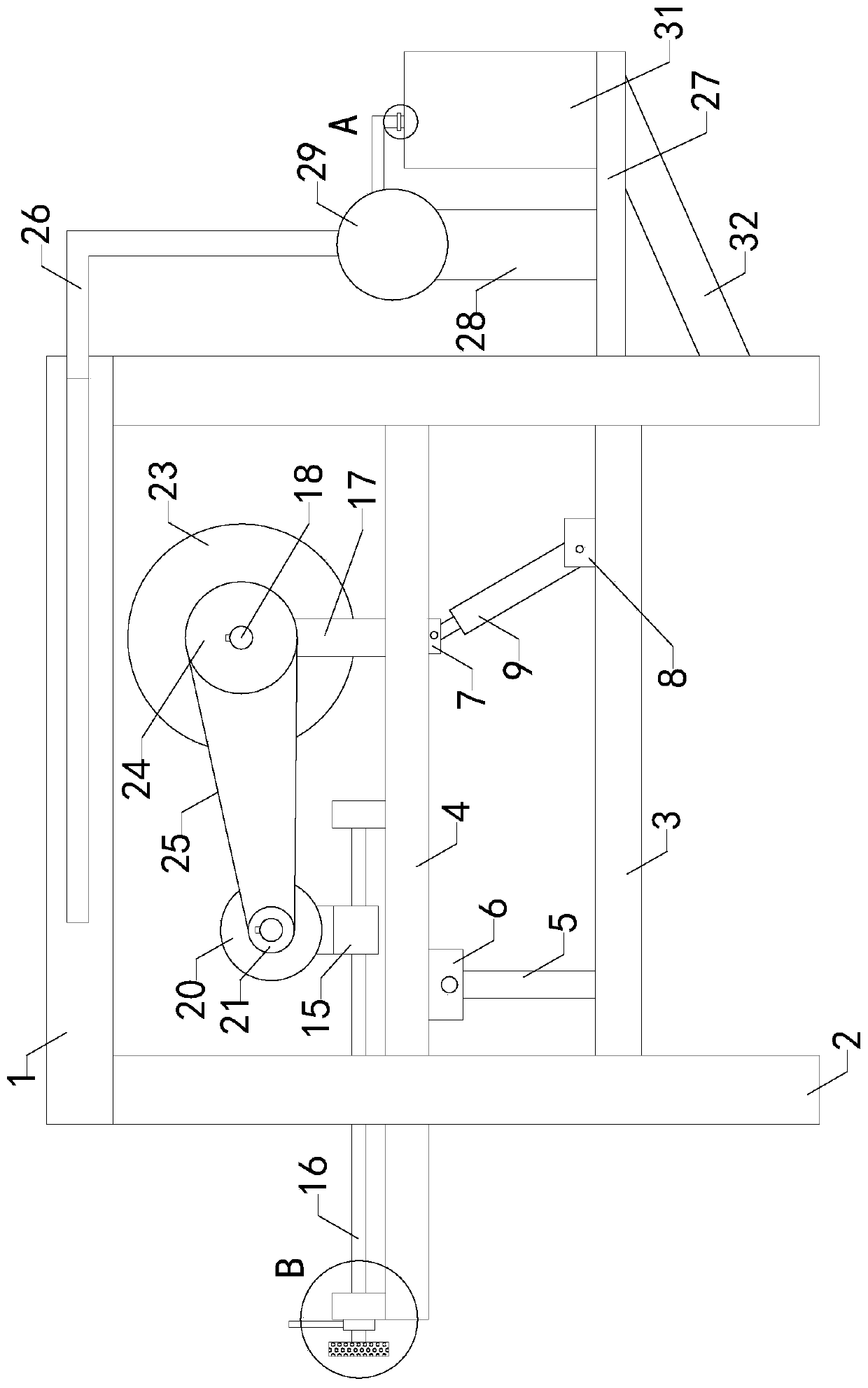
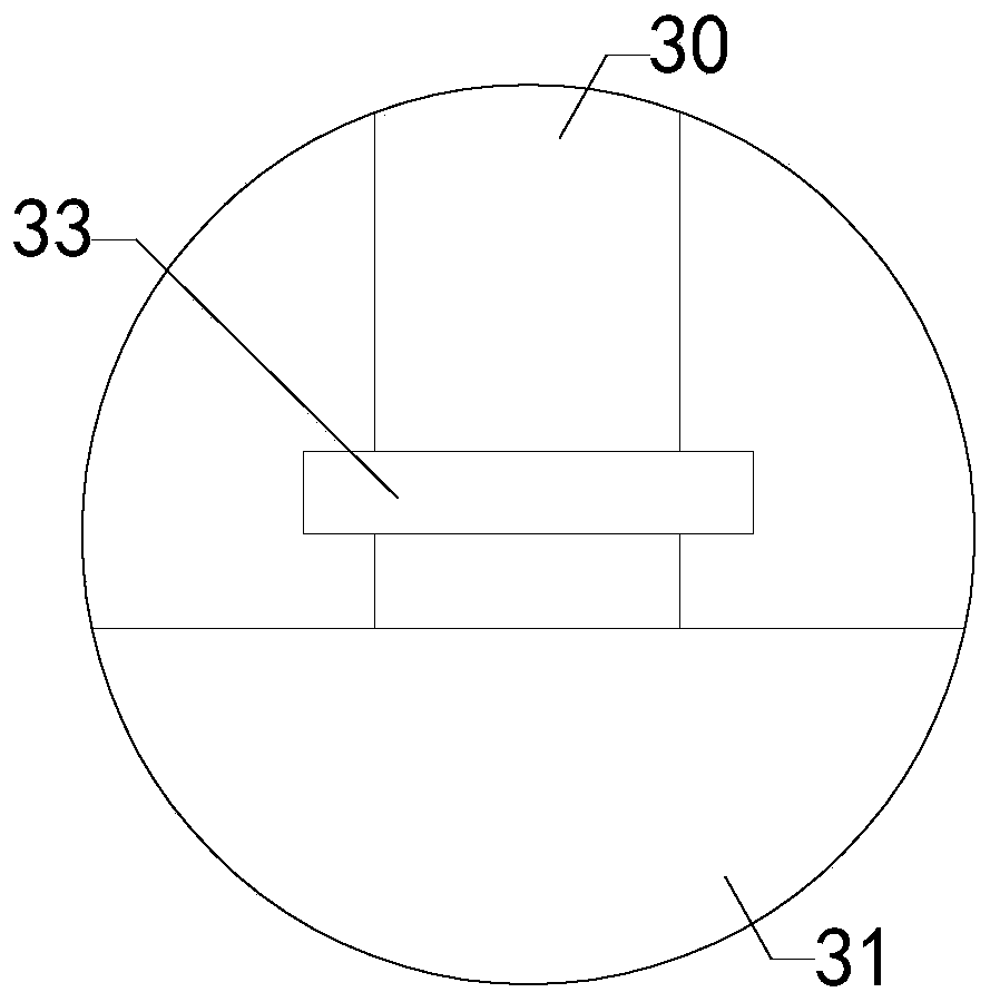
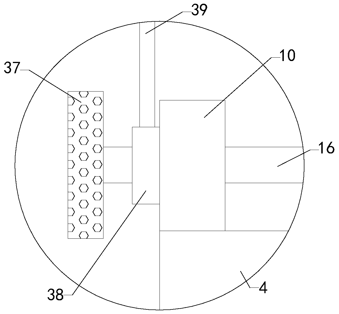
[0023] Such as Figure 1 to Figure 8As shown, a steel pipe cutting device used in the maintenance process of the drainage pipe network of the present invention includes a workbench 1, two sets of left legs 2 are respectively arranged on the left front side and left rear side of the bottom side wall of the workbench 1, and the workbench 1 Two sets of right outriggers are respectively provided on the right front and right rear of the bottom side wall, and the workbench 1 is provided with a transition hole; it also includes a connecting plate 3, a rotating plate 4, two sets of support rods 5, two sets of left fixing blocks 6, Right fixed block 7, lower fixed block 8, hydraul...


PUM


Abstract

The invention relates to the technical field of drainage pipe network accessory devices, in particular to a steel pipe cutting device used in the maintenance process of a drainage pipe network. The steel pipe cutting device is convenient to maintain and repair, and a cutting wheel is convenient to adjust so as to reduce the use limitation. The steel pipe cutting device comprises a worktable, a connecting plate, a rotating plate, two sets of supporting rods, two sets of left fixing blocks, a right fixing block, a lower fixing block, a hydraulic cylinder, a left fixing plate, a right fixing plate, a left rotating shaft, a right rotating shaft, a threaded rod, a rotary table, an adjusting plate, a front connecting rod, a rear connecting rod, a fixing rod and a driving shaft, wherein two groups of left supporting legs are respectively arranged at the left front side and the left rear side of the bottom side wall of the worktable; two groups of right supporting legs are respectively arranged on the right front side and right rear side of the bottom side wall of the worktable; the worktable is provided with a transition hole; the connecting plates are connected with the two sets of leftsupporting legs and the two sets of right supporting legs; and the bottom ends of the two sets of supporting rods are respectively connected with the front half area and the back half area of the lefthalf area of the top side wall of the connecting plate.

Description

technical field [0001] The invention relates to the technical field of drainage pipe network attachments, in particular to a steel pipe cutting device used in the drainage pipe network maintenance process. Background technique [0002] As we all know, the steel pipe cutting device used in the maintenance of the drainage pipe network is an auxiliary device used to cut long steel pipes during the maintenance of the drainage pipe network to make it easier to install. It has been widely used in the field; the existing steel pipe cutting device used in the maintenance process of the drainage pipe network includes a workbench. There are two sets of right outriggers on the right front side and the right rear side of the side wall, a motor is installed on the bottom side wall of the workbench, a cutting wheel is installed on the output end of the rear end of the motor, a transition hole is set on the workbench, and the top of the cutting wheel passes through the transition hole ; W...

Claims


Application Information

Patent Timeline
IPC IPC(8): B23D19/00B23D21/00B23D33/00
CPCB23D19/00B23D21/00B23D33/00
Inventor 刘汝群石婧曾天军
Owner 盐城瑾诚科技有限公司
Why Eureka
Try Eureka