Dropsonde ejection cylinder, ejection device and automatic feeding device

A technology of ejection device and radiosonde, which is applied to launch devices, instruments, transportation and packaging, etc., can solve the problems of limited flight height, difficult manual operation, and high cost of human and financial resources for detection, and achieves high versatility and convenient ejection. Effect

Active Publication Date: 2019-11-01
BEIJING INST OF RADIO MEASUREMENT
View PDF5 Cites 7 Cited by
  • Summary
  • Abstract
  • Description
  • Claims
  • Application Information

AI Technical Summary

Problems solved by technology

[0004] The technical problem to be solved by the present invention is to provide a drop-type radiosonde catapult, catapult device and automatic delivery equipment that can be used for high-altitude aircraft, so as to solve the problem of difficult manual operation, limited flight height, and excessive human and financial costs for detection. High-level problems, and the ejection device has been improved, only the mechanical structure is used, and each ejection barrel operates independently to avoid reliability problems caused by failures

Method used


Image

  • Dropsonde ejection cylinder, ejection device and automatic feeding device
  • Dropsonde ejection cylinder, ejection device and automatic feeding device
  • Dropsonde ejection cylinder, ejection device and automatic feeding device

Examples


Embodiment 1

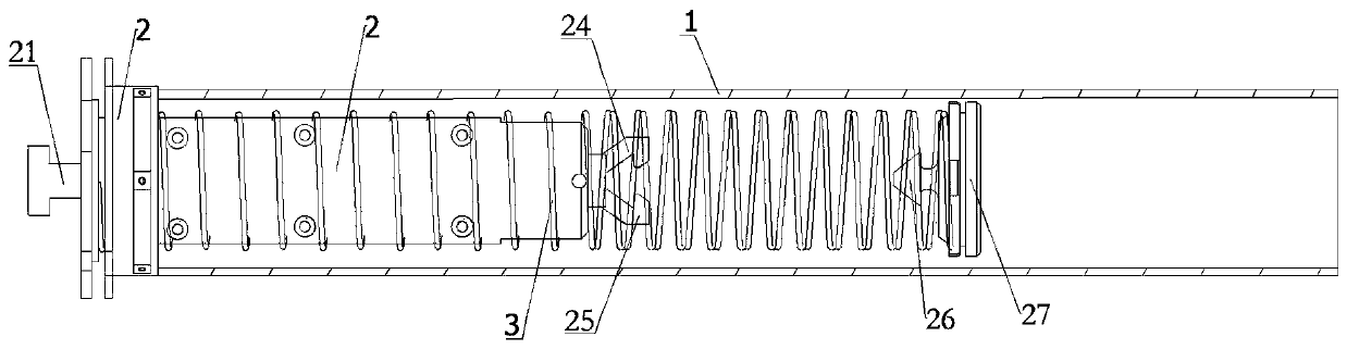
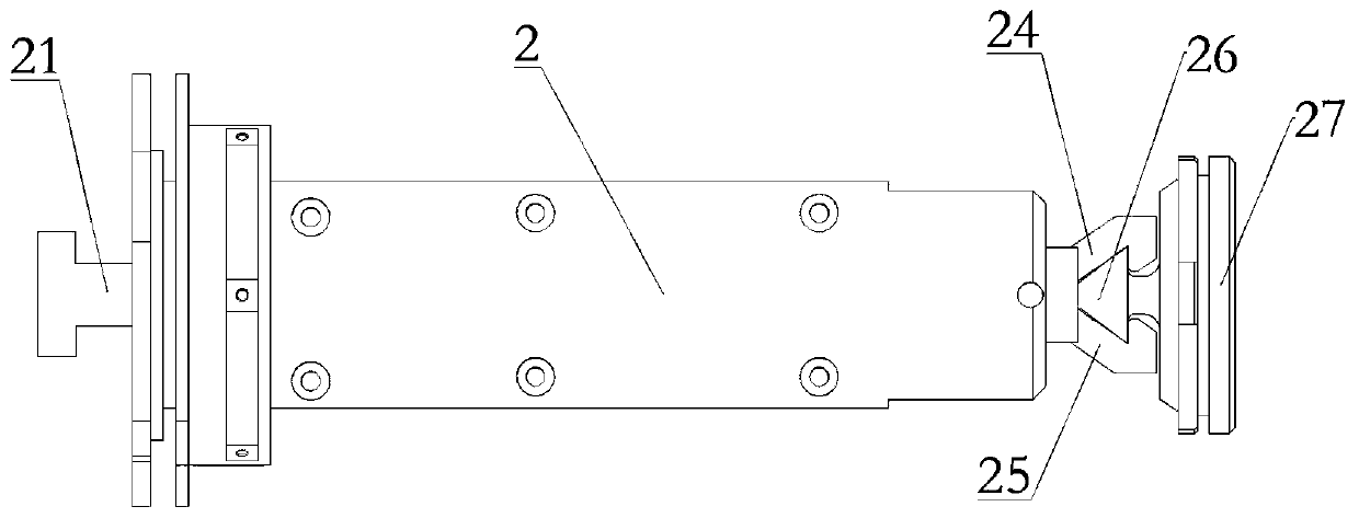
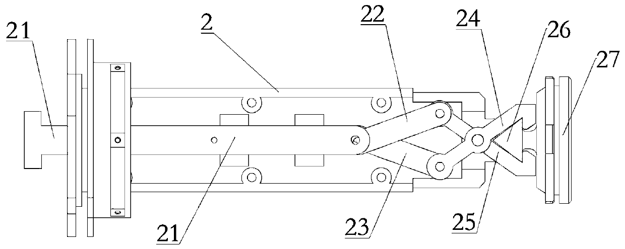
[0037] Such as Figure 1-Figure 3 As shown, a dropsonde ejection tube of this embodiment includes a tube body 1 , an elastic member 3 and a clamping release assembly located in the tube body 1 . One end of the elastic member 3 is connected to the barrel body 1, and the other end is connected to the push plate 27. The clamping release assembly is arranged along the axis of the barrel body 1. One side of the push plate 27 is connected to the push plate 27. The end of the clamping release assembly is clamped; the clamping release assembly is driven by the driving end of the ejection steering gear 107 to reciprocate along the axial direction of the barrel body 1, so as to clamp or release the push plate 27; Wherein, when the push plate 27 is clamped, the elastic member 3 is compressed, and after the push plate 27 is released, the radiosonde in the barrel body 1 is ejected under the action of the elastic member 3 .

[0038] The ejection barrel of this embodiment can effectively ej...

Embodiment 2

[0048] Such as Figure 4 As shown, a kind of ejection device of the present embodiment comprises the radiosonde ejection tube 105 described in Embodiment 1, the rotary frame wheel, the stepper motor 106, the ejection steering gear 107 and the delivery control system 110, and the ejection barrel is Several are installed in the rotary frame wheel perpendicular to the rotation direction of the rotary frame wheel. The stepping motor 106 is connected with the rotary frame wheel and drives the rotary frame wheel to rotate any radiosonde The ejection barrel corresponds to the driving end of the ejection steering gear 107, and the driving end of the ejection steering gear 107 drives the clamping release assembly in the corresponding radiosonde ejection barrel to move back and forth. The delivery control system 110 is used to After the drop-type radiosonde enters the launch state, the radiosonde is ejected out of the ejection barrel by controlling the connected ejection steering gear 1...

Embodiment 3

[0054] Such as Figure 1-Figure 5 As shown, an automatic delivery device in this embodiment includes the ejection device described in Embodiment 2 and the pod cabin body 400, the ejection device 100 is installed inside the pod cabin body 400, and the first support end cover , the second support end cover is fixed in the pod cabin body, the rotary frame wheel is coaxially arranged in the pod cabin body 400 and can rotate in the pod cabin body 400, the stepping motor 106, The ejection steering gear 107, the cabin door steering gear 109 and the launch control system 110 are respectively installed on the support end cover.

[0055] Specifically, when the pod control system sends out the ejection command, it first controls the pod door servo to open the door, and when the door opening sensor detects that the door is fully open, the ejection device starts to operate to eject the radiosonde ; When the radiosonde pops up smoothly, the hatch steering gear runs and closes, and when the...


PUM


Abstract

The invention relates to a dropsonde ejection cylinder, an ejection device and an automatic feeding device. The ejection cylinder comprises a cylinder body and a clamping and releasing component, an elastic piece and a push plate which are located in the cylinder body, the clamping and releasing component is arranged along the axis of the cylinder body, one end of the elastic piece is connected with the clamping and releasing component, the other end of the elastic piece is connected with the push plate, one side face of the push plate is connected with the elastic piece, the push plate can beclamped or and released by the clamping and releasing component, the clamping and releasing component is stressed to do a reciprocating motion in the axial direction of the cylinder body so as to clamp or and releasing the push plate, when the push plate is clamped, the elastic piece is compressed, and after the push plate is and released, a dropsonde in the cylinder body is popped out under theaction of the elastic piece. According to the ejection cylinder, the clamping and releasing component can be used for effectively ejecting the dropsonde in the cylinder body, so that the ejection is convenient; and the cylinder body is provided with the clamping and releasing component, each ejection cylinder is an independent ejection part, so that when multiple ejection cylinders are used, evenif one ejection cylinder is damaged, the use of other ejection cylinders cannot be influenced.

Description

technical field [0001] The invention relates to the technical field of meteorological detection and sounding equipment, in particular to a drop-type radiosonde catapult, a catapult device and automatic delivery equipment. Background technique [0002] The drop-type sounding is to drop the airsonde from an aircraft (such as an airplane, an airship, etc.) from a predetermined height, so as to obtain the atmospheric temperature, humidity, air pressure, wind direction, wind speed, etc. weather elements. It has a certain contribution to make up for the scarcity of high-altitude meteorological observation stations in areas such as oceans, deserts, low latitudes, and the southern hemisphere. It plays an important role in typhoon detection and forecasting, the reasonable distribution of the global upper-air meteorological observation station network, the acquisition of more comprehensive upper-air meteorological detection data, the establishment of atmospheric science theories, and...

Claims


Application Information

Patent Timeline
Patent Type & Authority Applications(China)
IPC IPC(8): B64D1/02B64D47/00G01W1/08
CPCB64D1/02B64D47/00G01W1/08
Inventor 彭文武张亚乾郑海堃刘泽林胡剑桥陈伟郭振杰马效培武云东侯景华
Owner BEIJING INST OF RADIO MEASUREMENT
Why Eureka
Try Eureka