Three-slope metal roof ridge connection joint and installation method thereof

A technology for metal roofing and installation methods, applied to roofing, roof covering, and roofs using flat/curved panels, etc., can solve problems such as failure of sealing measures, roof leakage, economic losses, etc., to avoid breakage, good waterproof function, Good telescopic deformation effect

Pending Publication Date: 2019-11-01
JINGGONG IND BUILDING SYST CO LTD
View PDF0 Cites 0 Cited by
  • Summary
  • Abstract
  • Description
  • Claims
  • Application Information

AI Technical Summary

Problems solved by technology

The same is true for steel roof metal panels. When exposed to the sun at noon in summer, the surface temperature of the metal roof can often rise to 70~80°C, which will cause the roof panels to expand in the length direction, and this phenomenon often causes some Nodes that can be normally waterproof at room temperature, due to self-expansion, some sealing measures will fail, resulting in large-scale water leakage on the roof, resulting in economic losses
[0003] With the increasing maturity of steel structure roofing technology, engineers have also noticed the problems caused by this phenomenon and proposed many specific solutions. However, the volume of modern industrial buildings is getting larger and larger, and factories with a length of more than 300 meters can be seen everywhere. , and with the diversification of shapes, a three-slope metal roof ridge appears, and how to realize the functions of waterproof and expansion at the joint node of the three-slope metal roof ridge has become a technical problem at this stage, because the nodes here need to consider three The expansion and deformation of the direction, the traditional one-way node method can no longer meet the structural requirements here

Method used


Image

  • Three-slope metal roof ridge connection joint and installation method thereof
  • Three-slope metal roof ridge connection joint and installation method thereof
  • Three-slope metal roof ridge connection joint and installation method thereof

Examples


Embodiment Construction

[0038] In order to make the technical means of the present invention and the technical effects that can be achieved more clearly and more perfectly disclosed, the following embodiments are provided hereby, and the following detailed descriptions are made in conjunction with the accompanying drawings:

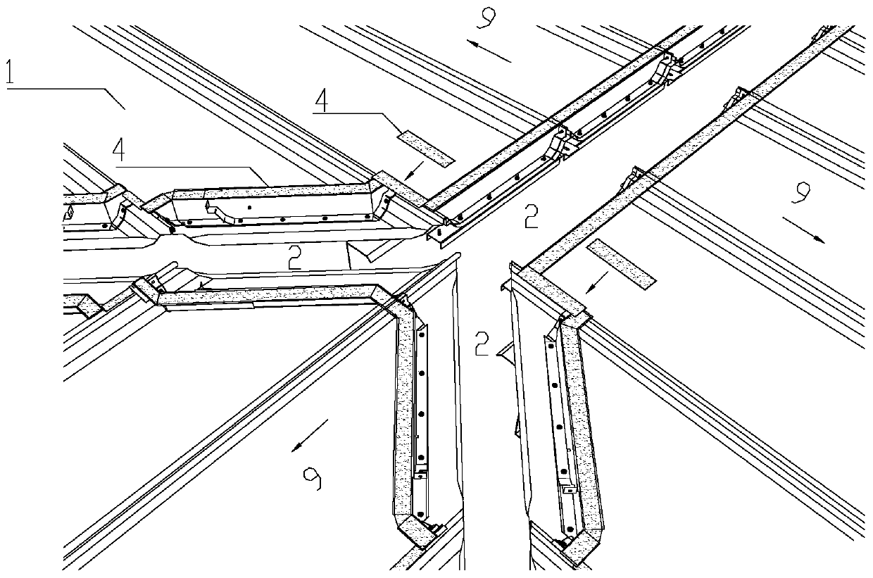
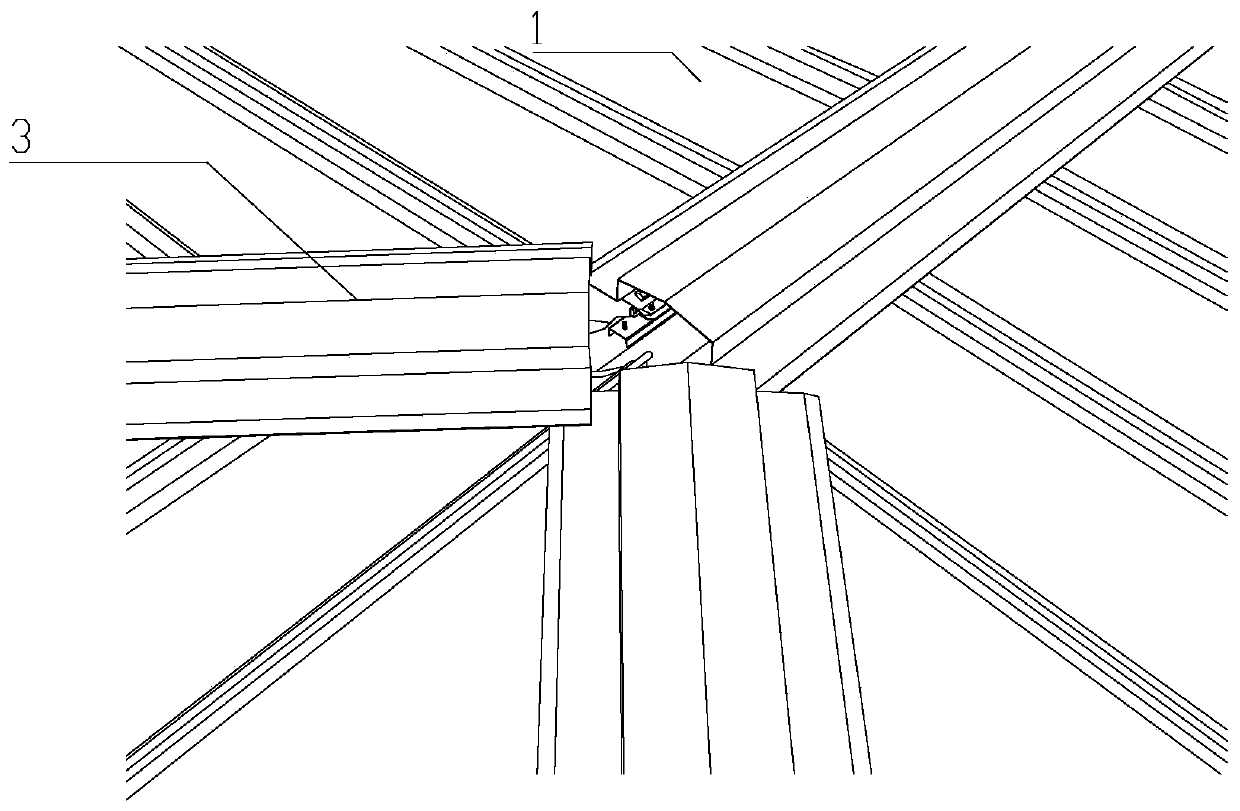
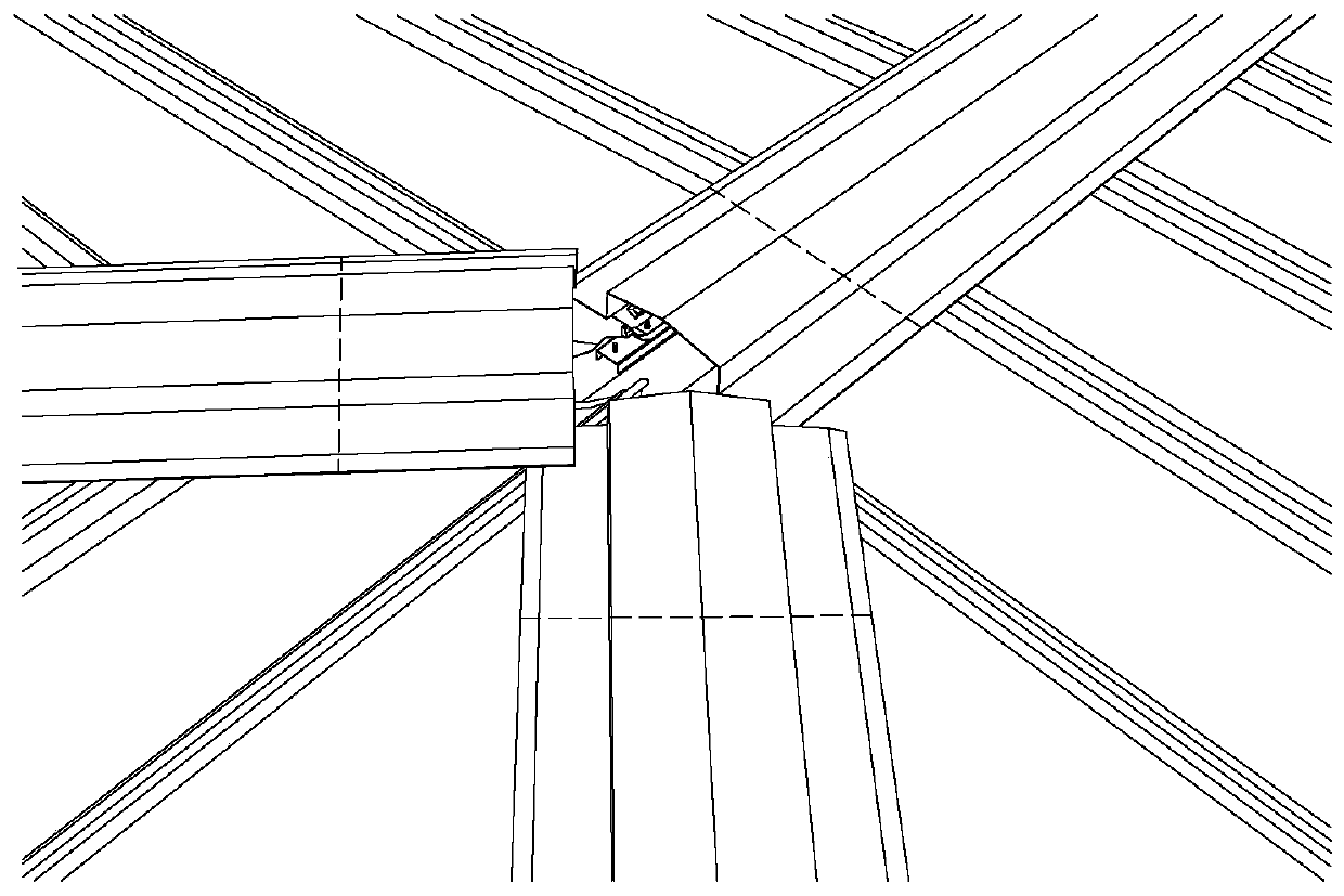
[0039] Such as Figure 1 to Figure 14 As shown, the ridge junction node of a three-slope metal roof in this embodiment includes three ridge junctions formed by three metal roof panels 1 with different slope directions. The three elastic ridge cover plates 3 at the ridge junction and the waterproof layer fixedly laid on the three elastic ridge cover plates 3 .

[0040] A first adhesive layer is laid between the elastic ridge cover plate 3 and the roof panel 1 , and a second adhesive layer is laid between the waterproof layer and the elastic ridge cover plate 3 . Continuous laying of the adhesive layer can better play a waterproof role.

[0041] Both the first glue layer and the...


PUM


Abstract

The invention provides a three-slope metal roof ridge connection joint and an installation method and relates to the technical field of metal roof enclosures. The three-slope metal roof ridge connection joint comprises three ridge connection positions formed by three metal roof sheathings with different slope directions and further comprises three elastic ridge cover plates fixedly installed at the three ridge connection positions and waterproof layers fixedly laid on the three elastic ridge cover plates. The installation method comprises the steps that M-shaped butyl rubber is pasted to roofsheathing corner positions; the roof sheathing corner positions are covered with the elastic ridge cover plates; lines are drawn on the elastic ridge cover plates; the M-shaped butyl rubber is pastedto line regions on the ridge cover plates; flexible waterproof rolls are laid; ridge battens are fixed through roof suturing nails; the waterproof rolls are tailored; and polyurethane sealant is applied. According to the three-slope metal roof ridge connection joint, the elastic roof cover plates are used for ridge waterproof edge closing and deform along with roof support sliding, and heat expansion and cold contraction internal stress can be released. A relatively good waterproof function is achieved at the joint positions, and a waterproof effect of the joint positions can still be guaranteed even through roof sheathing retraction is caused by heat expansion and cold contraction.

Description

technical field [0001] The invention relates to a ridge junction node of a three-slope metal roof and an installation method thereof, belonging to the technical field of metal roof enclosure. Background technique [0002] The difficult joints of the metal roof are all related to the sliding of the roof caused by the thermal expansion and contraction of the roof. Expansion with heat and contraction with cold is a basic property of an object. In general, it expands when heated, and shrinks when cooled. The same is true for steel roof metal panels. When exposed to the sun at noon in summer, the surface temperature of the metal roof can often rise to 70~80°C, which will cause the roof panels to expand in the length direction, and this phenomenon often causes some Nodes that can be normally waterproof at room temperature, due to self-expansion, some sealing measures fail, resulting in large-scale water leakage on the roof, resulting in economic losses. [0003] With the increas...

Claims


Application Information

Patent Timeline
IPC IPC(8): E04B7/06E04D3/38E04D3/40
CPCE04B7/06E04D3/38E04D3/40
Inventor 孔万裕倪庆两陈海勇梅军李镇江何稽明
Owner JINGGONG IND BUILDING SYST CO LTD
Why Eureka
Try Eureka