
Shaft-end power generation system and method for rail wagon

A technology for railway freight cars and power generation systems, applied in electrical components, electromechanical devices, electric components, etc., can solve the problem of rare application precedents for high-power electrical equipment, the supply of equipment that requires power, and the constraints of railway freight automation, informatization, Diversity and other issues, to achieve the effect of high stability, easy maintenance, and long life

Active Publication Date: 2019-11-01
CRRC SHANDONG CO LTD
View PDF9 Cites 1 Cited by
  • Summary
  • Abstract
  • Description
  • Claims
  • Application Information

AI Technical Summary

Problems solved by technology

At present, there is no conventional power supply system designed for railway freight cars in China, so it is impossible to provide demand for equipment that requires electricity, which seriously restricts the development of automation, informatization, and diversity of railway freight; at home and abroad, especially for high-power electrical equipment There are also few application precedents in power supply

Method used


Image

  • Shaft-end power generation system and method for rail wagon
  • Shaft-end power generation system and method for rail wagon
  • Shaft-end power generation system and method for rail wagon

Examples


Embodiment Construction

[0033] It should be noted that the following detailed description is exemplary and intended to provide further explanation of the present disclosure. Unless defined otherwise, all technical and scientific terms used herein have the same meaning as commonly understood by one of ordinary skill in the art to which this disclosure belongs.

[0034] It should be noted that the terminology used herein is only for describing specific embodiments, and is not intended to limit the exemplary embodiments according to the present disclosure. As used herein, unless the context clearly dictates otherwise, the singular is intended to include the plural, and it should also be understood that when the terms "comprising" and / or "comprising" are used in this specification, they mean There are features, steps, operations, means, components and / or combinations thereof.

[0035] Implementation example one

[0036] This embodiment discloses an axle end power generation system for railway freight c...


PUM


Abstract

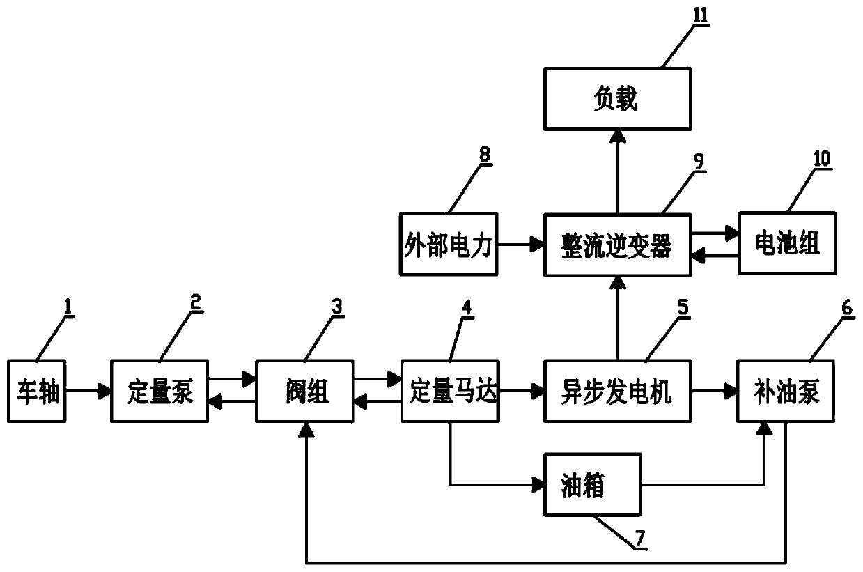
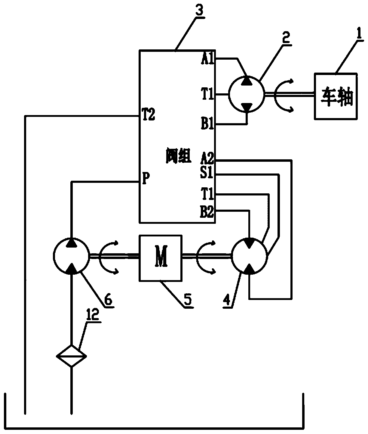
The invention provides a shaft-end power generation system and a shaft-end power generation method for a rail wagon. The shaft-end power generation system comprises a hydraulic transmission system anda power supply system. The hydraulic transmission system comprises a constant displacement pump, a constant displacement motor and an oil supplementing pump. The power supply system comprises an asynchronous generator and a rectification inverter. The constant displacement motor, the asynchronous generator and the oil supplementing pump are connected through a coupler and are in coaxial transmission, wherein the coaxial transmission in both the positive direction and the negative direction can be achieved. The constant displacement pump is installed at the axle end of an axle of the railway wagon and powered by the axle end of the axle. The asynchronous generator and the oil supplementing pump are powered by the constant displacement motor. The rectification inverter is connected with theasynchronous generator. The rectification inverter rectifies and inverts the electricity generated by the asynchronous generator and outputs the electricity to a load. The limit requirement of the rail wagon is met. The constant displacement pump, the constant displacement motor, the oil supplementing pump and the asynchronous generator can work in a two-way rotating mode. The electric power provided in the forward direction is equal to that provided in the reverse direction.

Description

technical field [0001] The present disclosure relates to the technical field of electrical equipment for railway locomotives, in particular to an axle end power generation system and method for railway freight cars. Background technique [0002] Railway freight is an important part of my country's three-dimensional transportation network, which has the advantages of large transportation volume, long distance, low cost, energy saving and environmental protection. At present, there is no conventional power supply system designed for railway freight cars in China, so it is impossible to provide demand for equipment that requires electricity, which seriously restricts the development of automation, informatization, and diversity of railway freight; at home and abroad, especially for high-power electrical equipment There are also few precedents for power supply. [0003] Application No. 200610156743.3 discloses an axle-driven generator for railway passenger cars, etc., which can...

Claims


Application Information

Patent Timeline
Patent Type & Authority Applications(China)
IPC IPC(8): H02K7/18
CPCH02K7/1823
Inventor 刘寅华周勇汉刘建斌李宝瑞王海静
Owner CRRC SHANDONG CO LTD
Learn More